Shop Work Page #4

This webpage shows the current jobs
being worked on in the shop.
Hope you enjoy the activity.
Page 1, Page 2, Page 3, Page 4, Page 5, Page 6, Page 7, Page 8, Page 9, Page 10, Page 11, Page 12, Page 13,
Page 14, Page 15, Page 16, Page 17, Page 18, Page 19, Page 20, Page 21, Page 22, Page 23, Page 24, Page 25,
Page 26, Page 27, Page 28, Page 29, Page 30, Page 31, Page 32, Page 33, Page 34, Page 35, Page 36, Page 37,
Page 38, Page 39, Page 40, Page 41, Page 42, Page 43, Page 44, Page 45, Page 46, Page 47, Page 48, Page 49, Page 50,
for more Shop Work.
Here in these (4) photos I am working on some parts for a fifth wheel hitch. In photos #1 & #2 I am milling the top of the tube off and also milling the sides of the tube down to the required dimension. In photos #3 & #4 I am taking a skim pass on the inside of the tube. The horizontal mill worked great for this type of job...


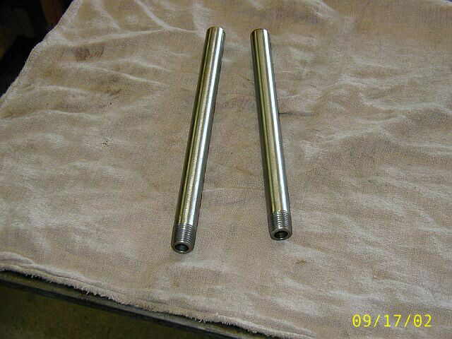
In these (4) photos I am making (2) hot tubes. In photo #1 I am turning the OD of the tube. Photo #2 shows drilling of the tube. I use solid stainless steel bar stock and drill the hole so there doesn't have to be any welding done to the top of the tube. Photo #3 shows the automotive length drill I use for drilling the tube and also the tube ready for threading. Photo #4 shows the (2) completed hot tubes...


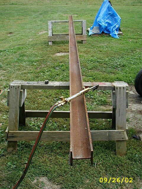
In these next (4) photos I have started work on a chain fall that will be used in my shop for lifting parts and lathe chucks / face plates onto the LeBlond lathe and the Lucas horizontal boring mill. The "H" beam is used but in great shape. There are (5) existing brackets welded to the "H" beam that I cut off with the torch and deburred. The size of the "H" beam is 4" X 4" X 20' X 3/8 thick. I am using an "H" beam instead of an "I" beam for the rail to minimize the height taken up by the system...


The parts being shown in these next (3) photos are the mounting plates that will be welded to the "H" beam and fastened to the trusses. Photo #1 shows cutting (4) pieces to length. Photo #2 shows how the plates will be located on the "H" beam and welded. Photo #3 shows drilling (2) 3/4" diameter holes for the threaded rod to go through. The mounting will become clearer to you as the project goes on...

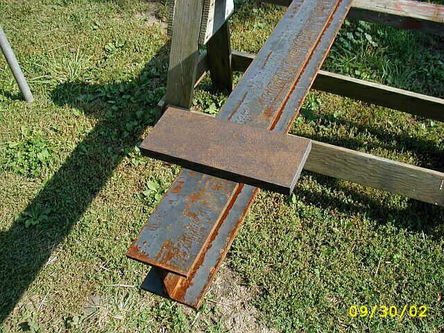
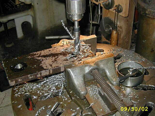
Photo #1 shows all (4) plates drilled for mounting the "H" beam. Photo #2 shows marking and laying out where each plate is going to be welded. Photo #3 shows the plate clamped and ready for welding...


Photos #1 & #2 show the welding has started...


These (2) photos show the mounting plates all welded to the "H" beam which is now ready for installation...


In these first (2) photos I am cutting the "C" channels to length. These will go up into the attic of the shop and stretch across (3) of the trusses. The third photo shows the only design problem I have with the location of the "H" which is driven by the locations of the machines I want it to be able to access. The problem is, how does the chain fall cross the line shaft?


Here I am finishing work up on more parts for a fifth wheel trailer. In photo #1 I am milling a slot in the (2) 3/8" thick plates. I welded them together so I could mill them both at the same time and have perfect alignment. In photo #2 the slot is all milled out. In photo #3 I have changed end mills, to a bigger 1/2" diameter end mill and completed all the finish passes by climb cutting. This really gives a nicer finish...


In photo #1 a friend of mine is helping out with the work on the chain fall construction. He is burning the holes in the "C" channel that the threaded rod will go through. Notice the other little helper in photo #1. He is checking the holes size for the threaded rod. Photo #2 shows one of the "C" channels up in the attic, in position, and the threaded rod in place. There will be (4) for these for holding the "H" beam up...


Here in these next (3) photos you can see the "H" going up into place. Not much to add here about the photos other then there is a lot of grunting going on...


In photo #1 the final tightening of the entire assembly is taking place. There is my oldest son, Joseph, up in the attic which you can't see in the photo. Photo #2 shows the finished "H" beam all mounted and ready for service. Thanks a lot guys for all your help...


Well its back to work. Here in these next (5) photos you can see the set/up and clamping used to align and clamp the 15 HP Innes cylinder into location. Photo #1 is looking in the cylinder bore towards the machine spindle. You can see how bad the bore is pitted on the compression end. Photo #2 shows getting things set/up. Photo #3 shows the indicator mounted in the machine spindle. Notice the angle of the indicator so it rides over the web in the exhaust port. Photo #4 is a view from the head side of the cylinder. Photo #5 shows my friend Ron Polle reading the indicator as it travels down the cylinder bore...


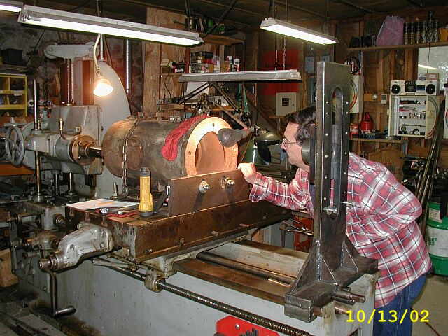
Photo #1 shows the cutter all mounted and ready for boring. Photo #2 shows the outboard bearing support all indicated and the stabilizing bar in position for boring...


These (3) photos show some of the cutting passes. Photo #3 is of the last pass and you can see how the bore has cleaned up...


These (2) photos are of machining the head mounting surface. Photo #1 shows the first pass around the cylinder head mounting surafce and Photo #2 shows the last pass...


Well its time to check out the work. In photo #1 I am indicating the bore in 90 degree increments to see how much taper I wound up with in the finished bore. The out-board bearing setup plays a big part in the final taper. The taper is .002 over an 18" long bore. I am real happy with that number. Photo #2 is of removing the Innis cylinder from the Lucas Horizontal Boring Mill...


Page 1, Page 2, Page 3, Page 4, Page 5, Page 6, Page 7, Page 8, Page 9, Page 10, Page 11, Page 12, Page 13,
Page 14, Page 15, Page 16, Page 17, Page 18, Page 19, Page 20, Page 21, Page 22, Page 23, Page 24, Page 25,
Page 26, Page 27, Page 28, Page 29, Page 30, Page 31, Page 32, Page 33, Page 34, Page 35, Page 36, Page 37,
Page 38, Page 39, Page 40, Page 41, Page 42, Page 43, Page 44, Page 45, Page 46, Page 47, Page 48, Page 49, Page 50,
for more Shop Work.
 |
Antique Gas Engine WebSite |
|
 Website designed and maintained by , Pavilion, NY.
Lunarpages Affiliate Program

Registered User #157284
Sun, Sparc, Ultra60 running Aurora 1.0 (RedHat Linux 7.3)
in mind, and are meant entirely for fun. No copyright infringements (if any) are done intentionally.