Shop Work Page #11

This webpage shows the current jobs
being worked on in the shop.
Hope you enjoy the activity.
Page 1, Page 2, Page 3, Page 4, Page 5, Page 6, Page 7, Page 8, Page 9, Page 10, Page 11, Page 12, Page 13,
Page 14, Page 15, Page 16, Page 17, Page 18, Page 19, Page 20, Page 21, Page 22, Page 23, Page 24, Page 25,
Page 26, Page 27, Page 28, Page 29, Page 30, Page 31, Page 32, Page 33, Page 34, Page 35, Page 36, Page 37,
Page 38, Page 39, Page 40, Page 41, Page 42, Page 43, Page 44, Page 45, Page 46, Page 47, Page 48, Page 49, Page 50,
for more Shop Work.
After making the first pass through the bore on the Famous cylinder I wasn't happy with the stability of the cutting tool. What I am going to do is make another bearing support that will mount directly to the cylinder and give the stabilizer bar more support throughout the entire bore length. In photo #1 you can see how I am going to mount the extra support bearing to the cylinder. Photo #2 shows the C-channel that will house the bearing getting (3) holes drilled...


Next, I need to make a housing for the brass support bearing. This housing will get welded to the C-channel. In photo #1 the housing end is faced off and the OD turned down to the diameter that will fit into the C-channel. In photos #2 & #3 you can see the drilling operation has started. Photo #4 shows the ID of the housing being bored. Photo #5 shows the chamfers cut and housing almost completed...


Below are (2) photos Dave Johnson sent me of the finished brasses for his 15 HP Titusville Olin restoration. They look real good...


In this photo you can see I have flipped the bearing support housing around and faced off the other end and chamfered the ID and OD...

Photo #1 shows the C-channel setup in the mill, centering up the center hole to bore out to except the bearing support housing. The housing will be pressed into the C-channel and then welded. Photo #2 shows something I have never done before. I used a metal cutting hole saw to open up the center hole to cut down on the amount of material I had to bore out. Photo #3 shows a fly cutter being used to bore the hole to a diameter of 2.300...


Photo #1 shows how I use a magnetic base indicator, with a flat tip, to measure how far I am indexing the tool bit in the fly cutter. This is a very easy and accurate way to achieve the proper hole size. Photo #2 shows the completed hole, bored to a diameter of 2.300...


In photo #1 I am drilling (2) holes that will be for set screws that will hold the split brass bushing in place and also control the amount of drag on the stabilizing bar. Photo #2 shows tapping the (2) Holes...


In photo #1 the bearing support housing is being pressed into the C-channel. Photo #2 shows the bearing support housing welded to the C-channel...


Now with the bearing support housing welded in place the bore should be indicated to see if it is true to the mounting surface of the C-channel. (the way it will be mounted on the cylinder) Photo #1 shows centering the existing bore on the vertical mill. (note; the C-channel is mounted on the vertical mill the way it will be mounted on the cylinder) Photo #2 shows running an indicator up and down the bore of the bearing support housing to see if the bore is out. It was. Photo #3 shows the Criterion boring head in action. Photo #4 shows the finished bore. Now the bore of the bearing support housing is true to the mounting surface...


Now to make the split brass bushing. Photo #1 shows turning the OD of the bushing. Photo #2 shows the ID bored and the ends chamfered, and being cut-off to length. Photo #3 shows the bushing inserted into the bearing support housing. (2) drill points where drilled in for the set screws and the brass bushing was also saw cut and deburred. The bearing support housing and bushing also received an oil hole for lubrication...


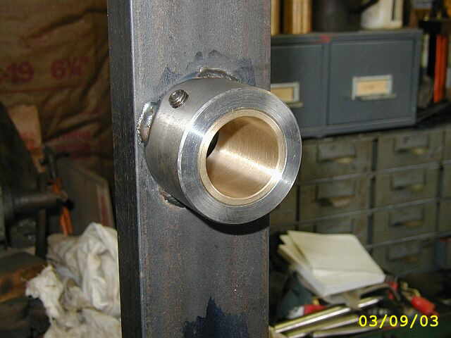
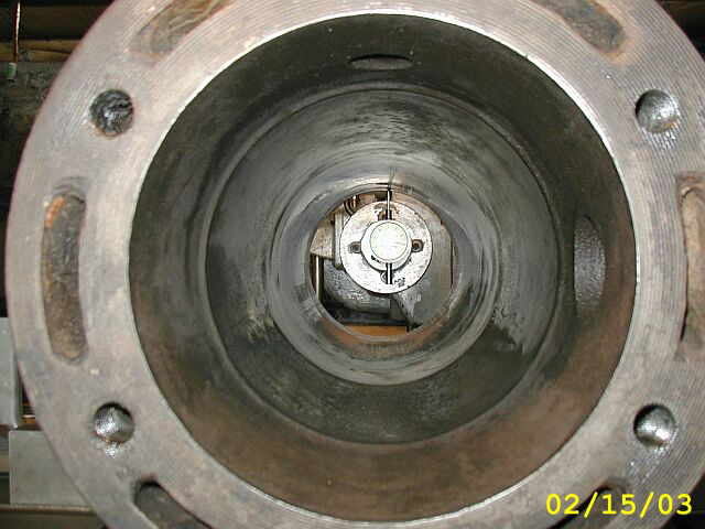
Photo #1 shows the bearing support all mounted on the cylinder and ready for action. In photo #2 we have started taking another pass through the cylinder bore. Shazam! No more tool chatter through out the entire length of the bore. Photo #3 is another view of the boring...


In these (3) photos I am getting ready to make one more roughing pass. In photos #1 & #2 you can see the bore is really cleaning up nice. Photo #3 shows the head end of the bore which was the worst. This is the end where all the debris was laying in the cylinder for who knows how long. Notice in this photo the bottom of the bore is almost all cleaned up...


Photo #1 is of the finish cut through the bore. I set the tool bit to take .004 off per side and took the feed down to .006 per revolution. Photo #2 shows the score card for how many passes it took to clean the bore up. Photo #3 is a before shot of the bore and photo #4 shows the completed bore. I wiped out the oil and chips with a rag and there is a little discoloring but this will all go away with honing. What a big difference between the (2) photos...


In this photo, all the tooling and support bars have been removed and I put a dial indicator in the machine spindle to tram all (4) quadrants and check for taper on the new bore. The bore came out nice and straight due to all the bearing support used for the setup...

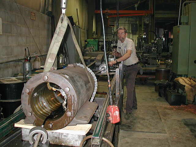
For honing of the bore I took the cylinder over to my friends shop, Corfu Machine. Dave Johnson has a nice honing machine they use for the manufacturing of hydraulic cylinders and it works out great for honing engine cylinders. Photo #1 shows getting the cylinder over to the honing machine. In photo #2 the cylinder is all mounted and secured in position with the honing tool all setup. Photo #3 is a close up of the honing tool at work. Photo #4 shows what it looks like from the operators point of view...


These (2) photos are of the completed bore. Photo #1 is a view from the crankshaft end of the cylinder. Notice the cross hatching. Photo #2 is of the head end of the cylinder and this was the bad end as far as pitting goes. Notice how nice this all cleaned up. The new bore is a diameter of 8.139 after boring and honing, with a total of .151 being removed to clean the bore up. Now to get the piston ready for the new bore...


Here in this photo I started making a new wrist pin...

In photo #1, Dave Yorks and myself are cleaning out the piston ring grooves. We are getting the piston ready to get metalized so it will fit the new cylinder bore. Photo #2 shows the piston all cleaned up...


In this photo I pressed out the brass bushing for the wrist pin and cleaned up the oil passage holes and the connecting rod...

Shop Work Continued on Page #12
Page 1, Page 2, Page 3, Page 4, Page 5, Page 6, Page 7, Page 8, Page 9, Page 10, Page 11, Page 12, Page 13,
Page 14, Page 15, Page 16, Page 17, Page 18, Page 19, Page 20, Page 21, Page 22, Page 23, Page 24, Page 25,
Page 26, Page 27, Page 28, Page 29, Page 30, Page 31, Page 32, Page 33, Page 34, Page 35, Page 36, Page 37,
Page 38, Page 39, Page 40, Page 41, Page 42, Page 43, Page 44, Page 45, Page 46, Page 47, Page 48, Page 49, Page 50,
for more Shop Work.
 |
Antique Gas Engine WebSite |
|
 Website designed and maintained by , Pavilion, NY.
Lunarpages Affiliate Program

Registered User #157284
Sun, Sparc, Ultra60 running Aurora 1.0 (RedHat Linux 7.3)
in mind, and are meant entirely for fun. No copyright infringements (if any) are done intentionally.