Shop Work Page #14

This webpage shows the current jobs
being worked on in the shop.
Hope you enjoy the activity.
Page 1, Page 2, Page 3, Page 4, Page 5, Page 6, Page 7, Page 8, Page 9, Page 10, Page 11, Page 12, Page 13,
Page 14, Page 15, Page 16, Page 17, Page 18, Page 19, Page 20, Page 21, Page 22, Page 23, Page 24, Page 25,
Page 26, Page 27, Page 28, Page 29, Page 30, Page 31, Page 32, Page 33, Page 34, Page 35, Page 36, Page 37,
Page 38, Page 39, Page 40, Page 41, Page 42, Page 43, Page 44, Page 45, Page 46, Page 47, Page 48, Page 49, Page 50,
for more Shop Work.
04/28/03
The following photos are of mounting the Abel Acme cylinder onto the bed plate. In the first photo you can see the studs going in. Photo #2 shows all (7) studs in the cylinder and photo #3 shows the cylinder in position getting ready to secure to the bed plate. Photo #4 shows the cylinder all mounted on the bed plate with the 1" heavy nuts started on the studs. Photos #5 & #6 show the cylinder all mounted on the bed plate...


05/05/03
I picked up a 16" DoAll metal cutting band saw which you can see in the following photos. There was a little work to be done on it before it was usable. One of the main things was it came from a shop that was 3 phase 480, (high voltage). Quite a bit of the wiring had to be changed by removing a step down transformer for the blade welder. Also, some of the wiring was old and fraid so it was replaced. I will be running the saw on 3 phase 220, (low voltage). The saw is back together and running great. What a machine...


05/11/03
This past weekend I did a varity of things. Photo #1 shows cutting a C-channel off of an old belt pulley and crankshaft that I had a ginder mounted on. The pulley is going to go back into service on the an engine. The rest of the photos are of doing some more setup on the Corliss box for the 60 HP Flickinger compressor engine. I used everything from the keyways in the machine platen, to planer gages, height gages/indicators, angle plates, to get things lined up properly.


05/12/03
Here in these next (4) photos I am melting the existing babbitt out of the connecting rod for the 3 HP Pohl diesel engine. Notice the grooves in the rod and cap for locking in the babbitt...


05/13/03
Here in these first (2) photos I have made up a new batch of babbitt for the main bearing. It's all ready, just need to get the rod set up. I had to make a special pin to fit the wrist pin bushing, this is the end in the (2) "V" blocks. The other shaft is a diameter of 2.247, .003 smaller then the diameter of the crankshaft journal. This will allow a few thousandths for shrinkage and scraping in. The entire set up will be mounted to a piece of jig plate before the pouring is done...


05/14/03
I have decided to mount this entire setup on a piece of 3/4" thick, ground aluminum jig plate. This will make for a good stable and accurate setup for pouring the connecting rod bearing. You can see in the photos I drilled and tapped some holes for clamping the wrist pin end of the connecting rod down. Also notice in the photos how the .060 thick brass shims are locating the shaft in the connecting rod. Now to get a couple of more "V" blocks and locate the shaft the bearing will be poured around...


05/15/03
Well the bearing gets poured. In the photos below you can see what the final setup came out looking like with the "V" blocks mounted on the aluminum jig plate. You can see the wooden sides that were made to form the sides of the new bearing. Notice too how all the moisture is cooked out of the entire setup before the wood and damming material are applied. This is a very important step. Next you can see the bearing all poured and then a photo of the setup all torn down. Tomorrow I will pull the new bearing apart when it reaches room temperature...


05/16/03
Well the first pour that was done didn't come out as good as I expected when I took it apart. I proceded to melt out the new babbitt and give it another try making some changes. Heres what I did. First I changed the setup by rotating the aluminum jig plate 90 degrees so that the setup was now in a vertical state. This allowed for the pouring of the babbitt in one whole side of the connecting rod. It also simplified the damming of the connecting rod and the wood. You can see this in the photos below. The moisture was again cooked out of the connecting rod and shaft, and re-setup. The pour was alot faster and no cooling was found in the new babbitt. The setup was allowed to cool and then taken apart. Now you can see how the new babbitt bearings look. This rod is now ready for action after a little fitting...


05/17/03
These first (5) photos are of a little project I have been wanting to get done. What it is going to be is a spanner wrench for taking the LeBond lathe chucks off and on. This also is one of the first projects for the DoAll bandsaw. I made a drawing of what the spanner wrench should look like and also a 1 to 1 plot for transfering the outline onto the steel. The bandsaw really works awesome and makes a lot of chips fast. It cut the 1/2" thick plate like it was butter. Next I am going to make a handle to weld onto it...


These (2) photos are of the 3 HP Pohl diesel engine crankshaft that we shipped out to Northeast Machine to get rebuilt. The bearing surfaces and journal were all built up and ground back to original size. I think these (2) photos of the crankshaft speak for themselves. The fellow to contact at Northeast Machine is Don, if you have any questions. They say there is no crank to large or small for their shop...


05/20/03 - 05/25/03
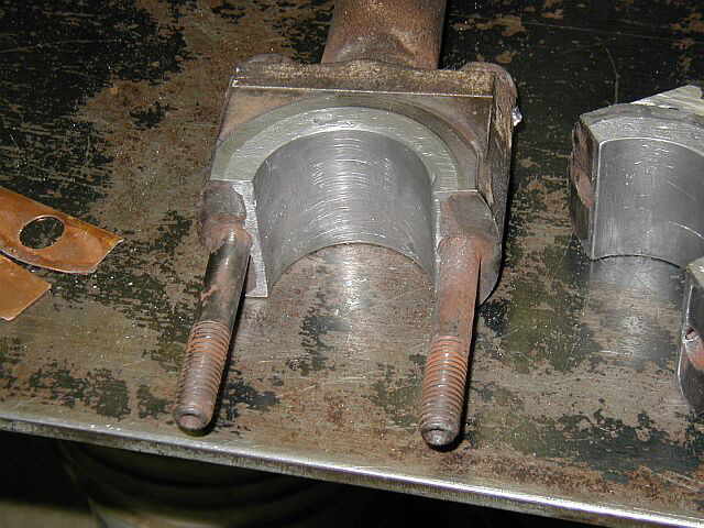
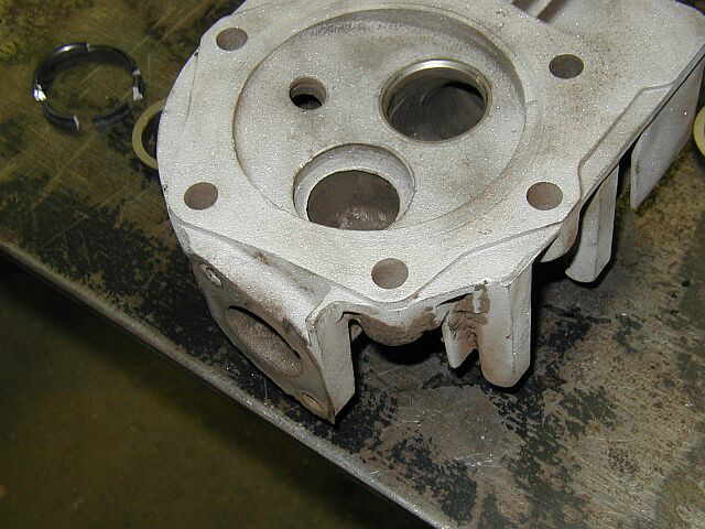
This first photo shows the completed spanner wrench for the LeBlond lathe chuck retaining ring. It came out real good and does a nice job of turning the retaining ring on and off. The following (8) photos show some work I have had to do on a 18 HP Kohler overhead valve engine that goes on my garden tractor. The intake valve seat came loose and hammered away at the aluminum head. I cut the old seat out with a dremel tool, and then broke it into small pieces to remove it. It had a flange on it that kept it locked into the head. You can see the flange in the enlarged photo. It's a little unclear but gives a good view of what it looked liked. I bored out the head for the new intake valve seat and then pressed it in. Now I need to re-cut the seat and then lapp the valve in....


Shop Work Continued on Page #15
Page 1, Page 2, Page 3, Page 4, Page 5, Page 6, Page 7, Page 8, Page 9, Page 10, Page 11, Page 12, Page 13,
Page 14, Page 15, Page 16, Page 17, Page 18, Page 19, Page 20, Page 21, Page 22, Page 23, Page 24, Page 25,
Page 26, Page 27, Page 28, Page 29, Page 30, Page 31, Page 32, Page 33, Page 34, Page 35, Page 36, Page 37,
Page 38, Page 39, Page 40, Page 41, Page 42, Page 43, Page 44, Page 45, Page 46, Page 47, Page 48, Page 49, Page 50,
for more Shop Work.
 |
Antique Gas Engine WebSite |
|
 Website designed and maintained by , Pavilion, NY.
Lunarpages Affiliate Program

Registered User #157284
Sun, Sparc, Ultra60 running Aurora 1.0 (RedHat Linux 7.3)
in mind, and are meant entirely for fun. No copyright infringements (if any) are done intentionally.