Shop Work Page #20

This webpage shows the current jobs
being worked on in the shop.
Hope you enjoy the activity.
Page 1, Page 2, Page 3, Page 4, Page 5, Page 6, Page 7, Page 8, Page 9, Page 10, Page 11, Page 12, Page 13,
Page 14, Page 15, Page 16, Page 17, Page 18, Page 19, Page 20, Page 21, Page 22, Page 23, Page 24, Page 25,
Page 26, Page 27, Page 28, Page 29, Page 30, Page 31, Page 32, Page 33, Page 34, Page 35, Page 36, Page 37,
Page 38, Page 39, Page 40, Page 41, Page 42, Page 43, Page 44, Page 45, Page 46, Page 47, Page 48, Page 49, Page 50,
for more Shop Work.
03/05/04
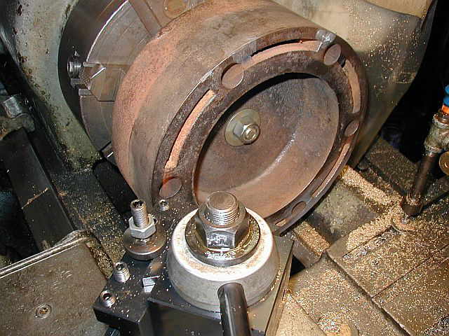
In these next (5) photos some parts had to be fabricated and some existing ones had to be altered to fasten the Braden cylinder to the machine table. Photo #1 shows an angle plate getting holes to mount on the rear flange of the cylinder. In photo #2 you can see the angle plate mounted to the machine table and cylinder. Photo #3 shows drilling holes in a new clamp bracket made out of a piece of angle. Photo #4 shows where it will be used. Note the piece of "C" channel used to act a "V" block for clamping down on the cylinder. Photo #5 ahows the clamping angle in place...


Time to start indicating the location of the cylinder on the machine. Photo #1 shows starting to indicate the head mounting surface. Photo #2 shows the shims used to get things positioned...


These (2) photos show what the bore looks like. Photo #1 is looking from the back side of the cylinder and photo #2 is from the head end where you can see all the damage to the bottom of the cylinder bore...


03/06/04
Here in these (3) photos the final indicating is completed. Photo #1 shows tramming the cylinder bore to map it out. When all done tramming the bore, every nook and crany is know. Photo #2 shows indicating the outboard bearing to position it on center with the machine spindle. Photo #3 shows everything in place and ready to start boring...


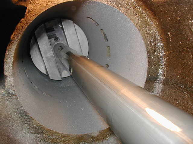
These next (4) photos show the boring. Photo #1 is looking in from the back side of the cylinder as the boring head is coming toward you. Photo #2 is taking from the head end and you can see how the bore is cleaning up. Photo #3 is of the finished bore. Photo #4 shows the hash makes on the cylinder showing that 7 passes were made to finish the new bore...


03/07/04
The next step is to hone the new bore. Photo #1 shows setting up the Sunnen hone. Photo #2 is taken from the back side of the cylinder showing the hone all setup. Photo #3 shows the honing being done. Photo #4 shows the new completed cylinder bore...


After completing the bore, a shell mill was put in the machine and a couple of passes were taken on the head mounting surface to true it up...

03/11/04 - 03/12/04
Here I am making a wrist pin for the 22 HP Witte. In photo #1 I am cutting a piece of 4150 bar stock. Photo #2 shows the OD of the bar turned and the end being faced off and chamfered. Photos #3 & #4 show the completed wrist pin...


03/13/04
A friend of mine, Mike Fuoco stopped over the shop to have a hex machined onto a part the he made for a small Flickinger air compressor engine. Photo #1 shows setting the part up in the indexing head on the vertical mill. Photo #2 shows a couple of the flats machined. Photo #3 shows the hex starting to take shape. Photo #4 shows the completed hex...


Photo #1 shows the old and the new valve guide side by side. Photo #2 shows Mike hand reaming the guide to fit the valve stem with an adjustable reamer...


03/14/04
This next series of photos show making a split bronze bushing for the wrist pin of the 22 HP Witte. Photo #1 shows facing off the end of some cored bronze material. Photo #2 shows the OD turned to size and boring starting on the ID. Photo #3 shows more of the boring and photo #4 shows the ID finished...


Photo #1 shows cutting the bushing off using a parting tool. Photo #2 shows the bushing cut off. Photo #3 is of cutting the bushing length wise on the band saw. It's a hard thing to do, split the bushing, after you just finish putting all the time and care into turning it...


03/17/04
In photo #1 you can see (2) cracks that need to be repaired in the Braden cylinder head. It's hard to see but in photo #2 I have drilled (2) .125 diameter holes at the end of the cracks to stop them from continuing on. Photo #3 shows the (2) cracks V'd out with the die grinder. In photo #4 the welding is almost completed...


03/18/04
In these next (3) photos the Braden head mounting surface is getting trued up. Photo #1 shows starting to take a cut on the gasket surface. Photo #2 Shows the surface starting to clean up. Photo #3 shows the finished head mounting surface all refaced...


03/19/04
This photo shows the final fitting and deburring of the split bushing for the 22 HP Witte Job. Once the piston rings come in they can be fitted and gapped, and the job will be complete...

03/20/04
In these next (3) photos the welds are cleaned up and a lot of deburring to the Braden cylinder is done. Photo #1 shows the welds on the water jacket all ground down and cleaned up. They are at the top of the cylinder in this photo. Photo #2 shows the tool I use to deburr both the transfer and exhaust ports to get rid of the razor sharp edge formed from boring. Photo #3 shows the finished Braden cylinder...


This is a photo of (3) parts I got back from the metal spraying shop. The piston in front is for a Watkins engine, there is an exhaust valve of a horizontal Myrick Eclipse on top of the Watkins piston that the stem has been metal sprayed. The piston behind the Watkins piston is the Braden piston...
03/21/04
In photo #1 I am facing off a piece of 3" diameter stock which will be part of the new packing gland plate for the Braden engine project. Photo #2 shows the end all faced and chamfered for welding...


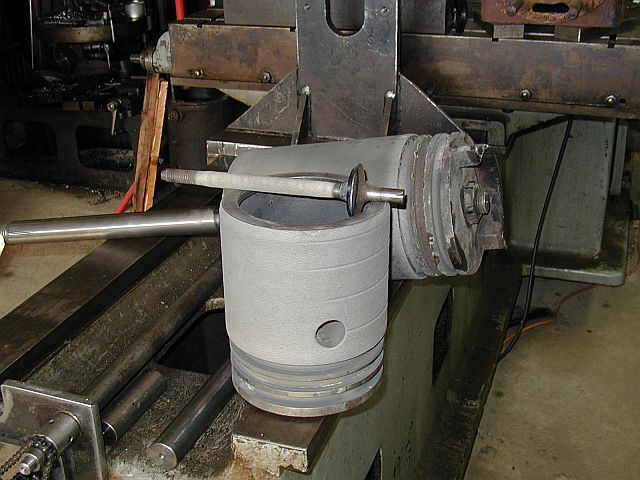
In these (5) photos the Watkins piston is being turned. In photo #1 you can see one of the first passes taken on the OD. Photo #2 shows starting to true the piston ring grooves. Photo #3 shows the piston ring grooves all trued up. Photo #4 shows the piston ring grooves completed, the OD turned to size, and the (3) oil grooves cut in the OD. Photo #5 shows the piston turned around in the lathe with a large cone center used to support the piston for cutting the large chamfer on the skirt of the piston...


Shop Work Continued on Page #21
Page 1, Page 2, Page 3, Page 4, Page 5, Page 6, Page 7, Page 8, Page 9, Page 10, Page 11, Page 12, Page 13,
Page 14, Page 15, Page 16, Page 17, Page 18, Page 19, Page 20, Page 21, Page 22, Page 23, Page 24, Page 25,
Page 26, Page 27, Page 28, Page 29, Page 30, Page 31, Page 32, Page 33, Page 34, Page 35, Page 36, Page 37,
Page 38, Page 39, Page 40, Page 41, Page 42, Page 43, Page 44, Page 45, Page 46, Page 47, Page 48, Page 49, Page 50,
for more Shop Work.
 |
Antique Gas Engine WebSite |
|
 Website designed and maintained by , Pavilion, NY.
Lunarpages Affiliate Program

Registered User #157284
Sun, Sparc, Ultra60 running Aurora 1.0 (RedHat Linux 7.3)
in mind, and are meant entirely for fun. No copyright infringements (if any) are done intentionally.