Shop Work Page #24

This webpage shows the current jobs
being worked on in the shop.
Hope you enjoy the activity.
Page 1, Page 2, Page 3, Page 4, Page 5, Page 6, Page 7, Page 8, Page 9, Page 10, Page 11, Page 12, Page 13,
Page 14, Page 15, Page 16, Page 17, Page 18, Page 19, Page 20, Page 21, Page 22, Page 23, Page 24, Page 25,
Page 26, Page 27, Page 28, Page 29, Page 30, Page 31, Page 32, Page 33, Page 34, Page 35, Page 36, Page 37,
Page 38, Page 39, Page 40, Page 41, Page 42, Page 43, Page 44, Page 45, Page 46, Page 47, Page 48, Page 49, Page 50,
for more Shop Work.
05/23/04
In this photo I have started laying out the locations for the (2) mounting holes and also the center for a blind hole that will be bored into the back brass for locating the brass half to the connecting rod...

Here in these series of photos I am doing a little experimentation on a Gray model engine. I am going to be lowering the compression by putting a spacer between the block and the cylinder head. This engine currently has a lot of compression and really wants to go to work. We'll see how we can get the Gray model to run by lowering the compression. Photo #1 shows dismantling the head, rocker arm, and push rod. Photo #2 shows the head and mounting studs removed...


In these (4) photos you can see the spacer starting to take shape. Photo #1 shows center drilling the spacer. Photo #2 shows step drilling the hole larger. Photo #3 shows boring the hole to 1.845 diameter. Photo #4 shows the spacer turned and faced, with the (2) faces now parallel to each other...


Photo #1 here shows transfering the head mounting hole locations to the spacer using transfer punches. Photo #2 shows the holes all transfered. Photo #3 shows using a wiggler to get the spindle on center. Photo #4 is of counter sinking the drilled hole...


Photo #1 shows center drilling the last hole. Photo #2 shows the holes all completed. Photo #3 shows the head on the engine with the studs screwed in to check location. The next step will be to make new studs that are 1.375 longer then the originals and also a longer push rod...


05/25/04
Here in these (5) photos I started making new longer studs to mount the head with the new spacer added. Photo #1 shows threading the stud using the tail stock to square up the die. Photo #2 shows the completed thread. Photo #3 shows the first stud completed and the spacer hanging on it. Photo #4 shows (3) of the (5) studs completed. The next (2) studs are a smaller diameter with a bastard size thread. These will have to be cut on the lathe. Photo #5 shows the spacer and head mounted on the engine being held on with the (3) studs...


05/31/04
Here in photo #1 you can see center drilling the small piece of round stock. Photo #2 shows the piece of round stock, .250 diameter being turned down to .201 diameter. Photo #3 shows the finished diameter of .201. Photo #4 shows starting to cut the 28 threads per inch...


These (2) photos show the completed thread. The second photo shows a brass nut on the newly cut thread. Now to cut the threads on the other end of the stud...


The first photo here shows the last (2) studs screwed into the cylinder. Photo #2 shows a new head gasket cut and slid over the studs with the spacer also on the studs. Photo #3 shows the head all mounted and torqued down...


A new longer push rod had to be made. Photo #1 shows turning the end on a piece of .1875 diameter brass. Photo #2 shows the end turned down to .146 diameter and the end rounded over. This also had to be done to the opposite end. Photo #3 shows the original push rod next to the new one that is 1.375" longer. Photo #4 shows all the other components along with the new push rod all assembled on the engine. Now to start the model Gray up...


06/01/04
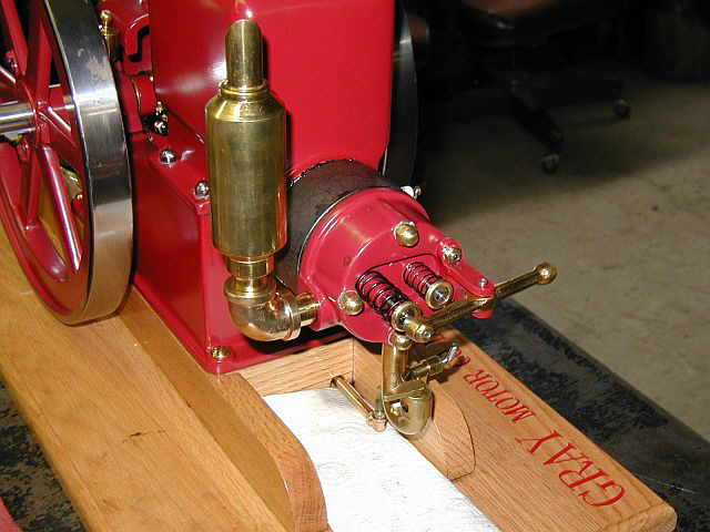
In these (2) photos you can see the model Gray engine running. The second photo shows the proud owner making some fine adjustments. By lowering the compression on this model, it has really mellowed it out, and has allowed us to run it slower. Please note: To make this alteration to the model, none of the original parts, piston, connecting rod, had to be altered. The spacer, studs, second head gasket, and push rod, were the only new parts needed to lower the compression. This ment if the changes didn't work, we could always get back to the original setup...


06/02/04
These (3) photos are of a 8 HP Goold Shapley & Muir piston that has been metal sprayed, so the OD can be brought up, to fit the new bore, with the proper clearance. Photo #1 shows the OD turned and the oil grooves rough cut into the OD. Photo #2 shows the OD and oil grooves completed. Photo #3 shows truing up the piston ring grooves. Now that the ring grooves are trued up, we can order some new piston rings...


06/05/04
These (2) photos are of a Lister clone engine my friend Ron Polle has put together. Also mounted on the skid is a 5KW generator. Ron had this on a portable cart but it will soon be mounted in a small addition Ron is building on his garage. This generating unit will be wired in to his main panel box to supply emergency power for the house. Believe it or not, this past winter, the Lister and generator saw 3 days of continuous action. Everything worked great...


06/08/04
Here I have started working on making a couple of new shafts for a stationary baler. You can see in the first photo how worn out the original shaft is and that it's also bent. Photo #2 shows facing the end of the new shaft. Photo #3 shows the shaft all faced off and a chamfer cut. Photo #4 shows the other end of the shaft all faced and chamfered, plus the rest of the shaft cleaned / polished...


In these (2) photos you can see that I have mounted the shaft vise on the vertical mill and are indicating the vise in...


Photo #1 shows taking the first pass of cutting a .250 wide keyway slot. Photo #2 shows the first pass complete...


06/09/04
Here in photo #1 the first slot is completed. Photo #2 shows a method I use to insure that the keyway slots are all in line. I attach a "V" block to the shaft and put a level it. Now the shaft can be moved in the shaft vise and brought back to level. You want to make sure your machine is level if you are going to rotate the shaft end for end...


In the first photo here you can see a 6" long slot being milled in the middle of the shaft. Photo #2 shows the completed slot on the left side of the shaft. Photo #3 shows the completed shaft next to the original shaft...


06/11/04 - 06/12/04
Here in these next series of photos you can see the last of the stationary baler shafts being completed. Photos #1, #2, & #3 show facing off the ends of the shaft and polishing the OD. Photo #4 shows starting to mill the keyway...


Photo #1 shows one of the keyways with a key in it. Photo #2 shows the method used to get the key ways in-line. Refer to the explaination above, dated 06/09/04 on how I did this. Photo #3 shows the last keyway done and the last stationary baler shaft completed...


Here in these (2) photos I needed to turn the diameter of a pin down for my tractor. Not a real big deal...


These (3) photos are of drilling the mounting holes in the 15 HP Olin brasses. Photo #1 shows the first hole center drilled and getting ready to drill. Photo #2 shows drilling in action. Photo #3 shows the (2) holes completed...


Shop Work Continued on Page #25
Page 1, Page 2, Page 3, Page 4, Page 5, Page 6, Page 7, Page 8, Page 9, Page 10, Page 11, Page 12, Page 13,
Page 14, Page 15, Page 16, Page 17, Page 18, Page 19, Page 20, Page 21, Page 22, Page 23, Page 24, Page 25,
Page 26, Page 27, Page 28, Page 29, Page 30, Page 31, Page 32, Page 33, Page 34, Page 35, Page 36, Page 37,
Page 38, Page 39, Page 40, Page 41, Page 42, Page 43, Page 44, Page 45, Page 46, Page 47, Page 48, Page 49, Page 50,
for more Shop Work.
 |
Antique Gas Engine WebSite |
|
 Website designed and maintained by , Pavilion, NY.
Lunarpages Affiliate Program

Registered User #157284
Sun, Sparc, Ultra60 running Aurora 1.0 (RedHat Linux 7.3)
in mind, and are meant entirely for fun. No copyright infringements (if any) are done intentionally.