Shop Work Page #25

This webpage shows the current jobs
being worked on in the shop.
Hope you enjoy the activity.
Page 1, Page 2, Page 3, Page 4, Page 5, Page 6, Page 7, Page 8, Page 9, Page 10, Page 11, Page 12, Page 13,
Page 14, Page 15, Page 16, Page 17, Page 18, Page 19, Page 20, Page 21, Page 22, Page 23, Page 24, Page 25,
Page 26, Page 27, Page 28, Page 29, Page 30, Page 31, Page 32, Page 33, Page 34, Page 35, Page 36, Page 37,
Page 38, Page 39, Page 40, Page 41, Page 42, Page 43, Page 44, Page 45, Page 46, Page 47, Page 48, Page 49, Page 50,
for more Shop Work.
06/23/04 - 06/24/04
In these next few photos you can see some babbitt bearings that I have to pour. Photo #1 shows the existing worn out babbitt bearings. Photo #2 shows cutting some round stock on the power hacksaw to make mandrels to simulate the shafts. Photos #3 & #4 show turning the OD of the first mandrel.


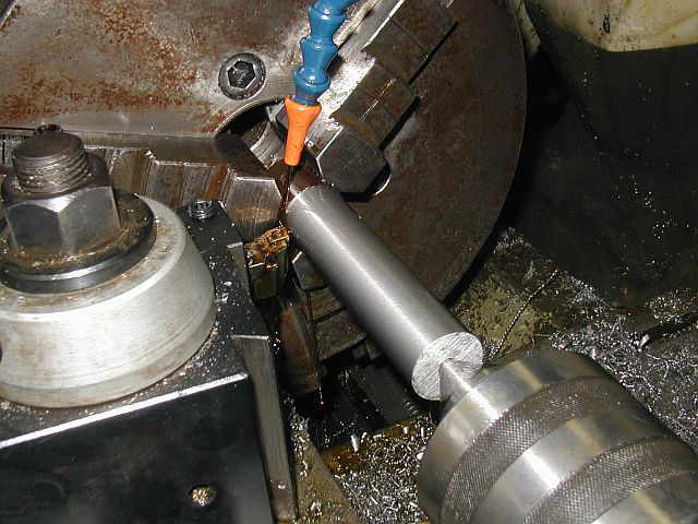
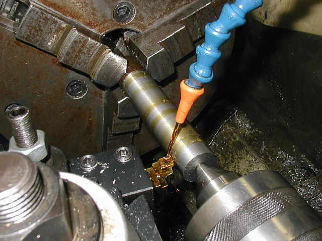
Photo #1 shows facing off the end of the mandrel. Photo #2 shows the first mandrel completed. Photo #3 shows all (4) mandrels completed. The diameters are 1.125, 1.250, 1.375, and 1.625.


06/25/04 - 06-26-04
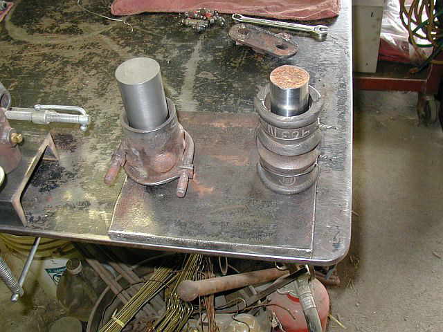
In photo #1 you can see the base of a fixture being drilled. The madrels will be welded to the base for pouring the babbitt around. Photos #2 & #3 show melting the babbitt out of the bearing housings. (Note: Make sure all the moisture is cooked out of the bearing housing before putting it into the molten babbitt in the ladle). Photo #4 shows (4) of the housings with the babbitt all melted out...


Photo #1 shows the (2) fixtures completed. (2) bearings can be poured on each fixture at a time. Photos #2 & #3 show the bearing housings located on the fixtures doing a test run on how things will mount. In photo #2 you can see how one of the bearing housings is also located against a 90 deg. angle block...


06/27/04
Photo #1 shows heating up the fixture. It is critical to get all the moisture out of the fixture or anything that will come in contact with the molten babbitt. Photo #2 shows heating up the babbitt. Notice the pine sticks used to see when the babbitt is hot enough for the pour. Photo #3 shows sooting up the mandrel so the babbitt won't stick to it. Photo #4 shows the first pour completed and rotating the housing on the mandrel to remove it...


Photo #1 shows the next fixture all set to pour. Everything is heated up, the madrels blackened, and dumb dumb surrounding the base of the housing to hold the babbitt in. Photo #2 shows getting the second fixture ready to pour again. Photo #3 shows all (7) bearings completed. Now the cleanup of the bearing housings, fitting of the shafts, and putting the oil grooves in is next. Photo #4 shows the first bearing being cleaned up and fitted...


06/28/04
Here in the first photo you can see the bearing all fitted to the shaft, shims in place, and the grease fitting installed. Photo #2 shows the oil groove in one of the other bearing blocks. Photo #3 shows all (7) of the completed bearings...


07/08/04
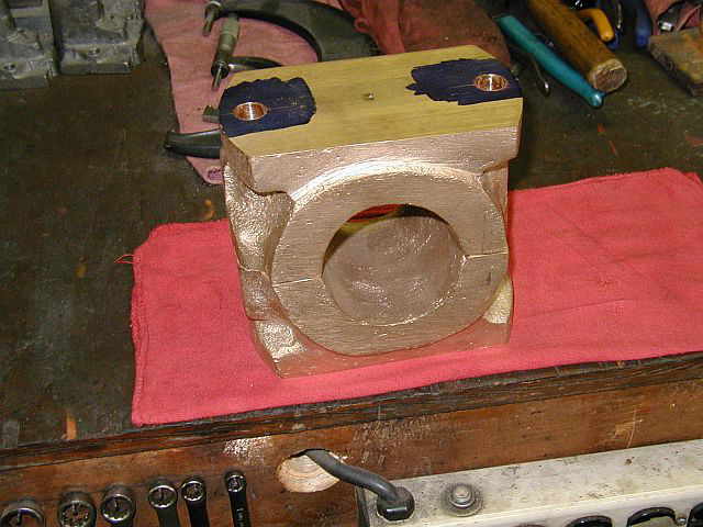
I have started working back on the 15 HP Titusville Olin brasses. Photo #1 shows the first time the (2) brass halves have been together. Photos #2, #3, & #4 show drilling the mounting holes in the second brass half. Photo #5 shows the brasses side by side and almost ready to be bolted together...


Now that the mounting holes are drilled I calculated how much shim I want to put between the (2) brass halves and removed half the thickness of the shim from each brass half. Photo #1 shows this being done in the shaper. Photo #2 shows the brasses and the shims in place all bolted together. Photo #3 shows mounting the bearing assembly in the four jaw chuck on the lathe. Photo #4 shows the bearing assembly all mounted. Notice the square used to make sure the bearings are perpendicular to the chuck face...


07/10/04
Here in photo #1 you can see the side of the bearing starting to clean up. Photo #2 shows one side of the bearing all faced off. Photo #3 shows my friend Ron Polle boring the hole, truing up the ID. Photo #4 shows the ID trued up and the bearing ready to be rotated 180 degs in the chuck. The final bore ID will be completed when the bearing is rotated in the lathe chuck...


Also started was work on a 8 HP Associated cylinder. This cylinder needs to be bored. In photo #1, notice the score marks made by the wrist pin. The wrist pin scored both sides of the cylinder bore. Also in photo #1 you can see the back end of the bore has been cleaned up a long with the cylinder mounting surfaces. These will be used to set up the cylinder on the Lucas Horizontal Boring Mill. Photos #2 & #3 show drilling holes in an angle plate to help support the cylinder when boring...


07/14/04
Photo #1 shows the bearing ID being indicated after flipping it over 180 degs. in the 4 jaw lathe chuck. Photo #2 shows starting to face the second side...


Photo #1 shows the second face all machined with the bearing mounting surface width, and bearing width, that will fit between the crank shaft throughs, machined to size. Photo #2 shows starting to finish bore the final ID. Photo #3 shows the completed ID...


07/20/04
In these next (4) photos the 45 deg. chamfer is being cut on the rod bearing. Photo #1 shows the 45 deg. chamfer starting to take shape. Photo #2 shows the 45 deg. chamfer on the first side completed. Photo #3 shows the bearing flipped over 180 deg. in the lathe chuck, and the 45 deg. chamfer being cut. Photo #4 is of the chamfers completed on both sides of the bearing. Now all that's left to do is drill and tap the oil hole, put oil grooves in the bearing surface, drill and tap a .25-20 thread for the nut locking strap, and bore a 1" diameter hole for locating the bearing on the connecting rod...


07/25/04
Photo #1 shows drilling the oil hole in the bearing. Photo #2 shows the oil all drilled and tapped and ready for the wiper...


The first photo here shows picking up the center of the back bearing with a wiggler. Photo #2 shows using a 7/8" diameter endmill to put a 1" diameter counter bored hole, X .250 deep in the back bearing. Photo #3 shows finishing the counter bore to a 1" diameter with a boring head. Photo #4 shows the completed counter bored hole...


On the second brass bearing half a hole is drilled and tapped in the center. This tapped hole will mount a 1/8" thick steel strap that will butt up against the nuts that hold the bearing to the connecting rod. This will act as a locking device for the nuts...


These (2) photos show the completed breaings. Notice the oil grooves cut in with a small ball endmill, using the die grinder...


Shop Work Continued on Page #26
Page 1, Page 2, Page 3, Page 4, Page 5, Page 6, Page 7, Page 8, Page 9, Page 10, Page 11, Page 12, Page 13,
Page 14, Page 15, Page 16, Page 17, Page 18, Page 19, Page 20, Page 21, Page 22, Page 23, Page 24, Page 25,
Page 26, Page 27, Page 28, Page 29, Page 30, Page 31, Page 32, Page 33, Page 34, Page 35, Page 36, Page 37,
Page 38, Page 39, Page 40, Page 41, Page 42, Page 43, Page 44, Page 45, Page 46, Page 47, Page 48, Page 49, Page 50,
for more Shop Work.
 |
Antique Gas Engine WebSite |
|
 Website designed and maintained by , Pavilion, NY.
Lunarpages Affiliate Program

Registered User #157284
Sun, Sparc, Ultra60 running Aurora 1.0 (RedHat Linux 7.3)
in mind, and are meant entirely for fun. No copyright infringements (if any) are done intentionally.