Shop Work Page #28

This webpage shows the current jobs
being worked on in the shop.
Hope you enjoy the activity.
Page 1, Page 2, Page 3, Page 4, Page 5, Page 6, Page 7, Page 8, Page 9, Page 10, Page 11, Page 12, Page 13,
Page 14, Page 15, Page 16, Page 17, Page 18, Page 19, Page 20, Page 21, Page 22, Page 23, Page 24, Page 25,
Page 26, Page 27, Page 28, Page 29, Page 30, Page 31, Page 32, Page 33, Page 34, Page 35, Page 36, Page 37,
Page 38, Page 39, Page 40, Page 41, Page 42, Page 43, Page 44, Page 45, Page 46, Page 47, Page 48, Page 49, Page 50,
for more Shop Work.
09/28/04
With the bearing support all mounted and positioned, I decided to re-indicate the cylinder to insure it's location and that nothing had moved. Photo #1 shows indicating / tramming the bore. Photo #2 shows re-indicating the mounting flange of the cylinder. Photo #3 shows getting the cylinder back on centerline with the HBM machine spindle...


Photo #1 here shows what the support bearing looks like all mounted and positioned. A short bar is put into the machine spindle to check position. Photo #2 shows an indicator set up for the end of travel when boring through the cylinder. Photo #3 shows another indicator setup to be able to return to the home position. Sometimes the indicators are not needed but they add extra insurance...


Well it's time to start boring. Photo #1 shows the first pass being taken with the boring tool setup to just hit the high spots. This pass verifies all my numbers from setting up the cylinder. Photo #2 shows the first pass from the head end of the cylinder. Photo #3 shows material now being removed on the second pass. Photo #4 is taken from the head end after about 3 passes...


These (2) photos are just a few extra shots of boring the 8 HP Associated cylinder...


These next (2) photos are of some work done to the 60 HP Flickinger sideshaft drive gear. Photo #1 shows drilling a .312 diameter hole over the keyway to tap for a 3/8-16 set screw. This set screw will help hold everything in position when drilling the tappered hole for the taper pin which will lock the bronze gear to the sideshaft. Photo #2 shows tapping the hole to a 3/8-16 thread...


09/29/04
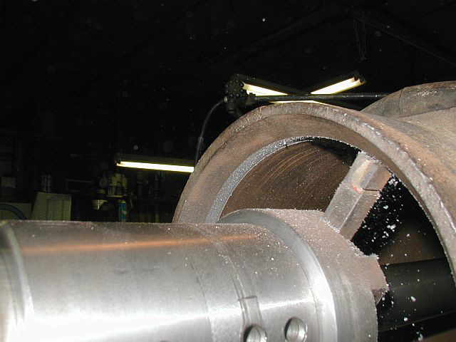
The first photo here shows how many passes were taken to clean the bore up. A total of (4) passes were taken with a total of .086 of material removed. (.043 / side) With the stability of the setup, .010 per / side was able to be removed per pass. Photo #2 shows the setup torn down, looking from the head end of the new bore. Photo #3 is looking from the crankshaft end of the cylinder. The spots in the bottom of the cylinder are from oil that was used on the stabilizing bar were it went through the bearing support. Photo #4 is just another shot of the new bore...


Photo #1 shows getting the Sunnen hone setup for honing the new bore. Photo #2 shows the hone in action. Photo #3 shows the new bore after honing. Photo #4 is a closeup of the bore, trying to show the cross hatch pattern achieved from the honing...


This photo shows the bronze gear mounted on the sideshaft with the key in place and the set screw tightened. Now we're ready to taper drill the hole for the taper pin...

10/01/04 - 10/02/04
Time to take the 8 HP Associated off of the Lucas HBM. Photo #1 shows removing the cylinder from the machine table with the chain fall. Photo #2 shows a 20 HP Evans cylinder ready to get loaded onto the HBM. All that has to be done to this cylinder is to machine the surface for the head mounting. Photo #3 shows the 20 HP Evans cylinder up on the machine table...


Photo #1 shows the sideshaft and bronze gear for the 60 HP Flickinger being drilled for a #9 taper pin. Photo #2 shows looking at the end of the sideshaft. Notice the chain fall supporting one end of the 6' long sideshaft. Photo #3 shows finishing the step drilled hole with the taper drill. This step is a hand operation...


It took about 8 hands to assemble the sideshaft, crank gear, and side shaft housing together. In the first photo Stiles and Ron are helping me do this. In photo #2 you can see what the finished assembly looks like with the taper pin installed...


Time to get the 15 HP Olin brasses / bearings back in the lathe. I received the crankshaft dimensions I needed to complete them and the first photo shows setting them up in the lathe. Photo #2 shows Ron helping out by rough boring the ID of the brasses...


This photo shows cutting a .004 thick paper gasket for the sideshaft bearing housing. Notice the use of the magnets to help hold the gasket in place while cutting it. This sideshaft assembly is now ready to mount on the engine...

This photo shows a project I am just starting, putting a 3 HP Leeson 3 phase motor on my Hendy Shaper. The motor I took off the shaper is a 1 HP single phase motor that believe it or not didn't have enough power when really working the shaper. My friend Steve Cole found this 3 HP 3 phase Leeson motor at a surplus store in Rochester, NY that looks like it was made for the shaper. I am going to make a subplate to mount the motor to the existing mount on the shaper and then things will line up great. Also might have to make a pulley. This photo shows the motor approximately in location. Thanks Steve for finding the Leeson motor...

10/03/04 - 10/04/04
I know everyone who follows this website is sick of looking at Olin Brasses, but they're almost completed. These (3) photos show the first stage of facing off one side of the bearings. Photos #1 & #2 show facing the first side of the bearing. Photo #3 shows facing the bearing side surface to the proper width...


The first photo here shows the first side of the bearing completed. Photo #2 shows rotating the bearing 180 deg. in the (4) jaw chuck and indicating the ID so the other side of the bearing can be faced. Photo #3 show the bearing faced to the proper width and the ID finished to size...


10/06/04 - 10/07/04
This first photo shows putting a chamfer on the ID of the bearing assembly. Photo #2 shows rotating the bearing around in the (4) jaw chuck 180 deg. and centering it up on the ID using a large cone center. Photo #3 shows the bearing brasses in the drill press with a 3/8 NPT thread being tapped for the oil pickup...


The bearing brasses are finally taken apart and the half that mounts to the connecting rod is put in the vertical mill and a pocket machinied. Photo #1 shows a 1/2 diameter center cutting end mill plunged into the bearing half, .250 deep. Photo #2 shows opening the pocket diameter to .875. Photo #3 shows finishing the pocket diameter to 1.003 with a boring head. Notice, one tooth of the end mill is used for the tool bit in the boring tool...
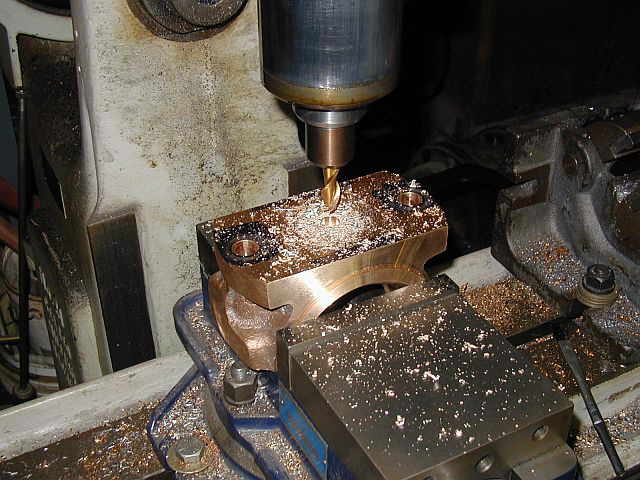


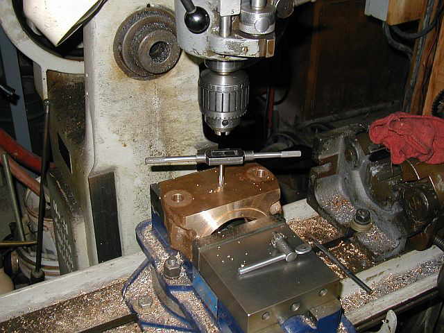
Photo #1 shows a 1/4-20 thread being tapped in the other bearing half for mounting a keeper strap to the bearing after everything is assemblied. This strap keeps the nuts from backing off when the engine is running. Photo #2 & #3 show each bearing half all deburred and cleaned up. Also in photo #3 you can see the oil grooves that were put in with a ball type end mill using a high speed grinder in each bearing half...


This photo is of starting to setup a new job in the vertical mill where some bases of hot tube chimneys need to be machined and mounting holes drilled. These are brand new castings..

10/09/04 - 10/10/04
To clamp the hot tube chimneys tight in the "V" blocks in the vertical mill, I made a real shallow "V" block. Photo #1 shows drilling a .250 diameter hole at the bottom of the "V". Photos #2 & #3 show cutting the "V" on the bandsaw. Photo #4 shows trimming the "V" blocks length on the power hacksaw...


Photo #1 shows cutting (2) pieces on the power hacksaw that will get welded to the "V" block. Photo #2 shows welding the (2) straps to the "V" block. Photo #3 shows what the "V" block assembly looks like. Photo #4 shows what the entire setup looks like and starting to take a few passes to clean up the hot tube mounting surface...


My friend Ron Polle stopped over the shop and helped out milling the hot tube chimneys. In photo #1 you can see Ron running the vertical mill. Photo #2 shows the chimney mounting surface all cleaned up. Photo #3 shows the chimney flipped over and the top surface cleaned up. Photo #4 shows another type of chimney in the fixture getting trued up and (2) slots milled in each end...


10/11/04
These (2) photos show the work continuing on machining the rest of the hot tube chimneys...


The first photo shows drilling a hole in the side of the hot tube chimney where the gas will enter. Photo #2 shows tapping the hole to a 1/2 NPT thread. Photo #3 shows the completed hot tube chimneys...


Shop Work Continued on Page #29
Page 1, Page 2, Page 3, Page 4, Page 5, Page 6, Page 7, Page 8, Page 9, Page 10, Page 11, Page 12, Page 13,
Page 14, Page 15, Page 16, Page 17, Page 18, Page 19, Page 20, Page 21, Page 22, Page 23, Page 24, Page 25,
Page 26, Page 27, Page 28, Page 29, Page 30, Page 31, Page 32, Page 33, Page 34, Page 35, Page 36, Page 37,
Page 38, Page 39, Page 40, Page 41, Page 42, Page 43, Page 44, Page 45, Page 46, Page 47, Page 48, Page 49, Page 50,
for more Shop Work.
 |
Antique Gas Engine WebSite |
|
 Website designed and maintained by , Pavilion, NY.
Lunarpages Affiliate Program

Registered User #157284
Sun, Sparc, Ultra60 running Aurora 1.0 (RedHat Linux 7.3)
in mind, and are meant entirely for fun. No copyright infringements (if any) are done intentionally.