Shop Work Page #32

This webpage shows the current jobs
being worked on in the shop.
Hope you enjoy the activity.
Page 1, Page 2, Page 3, Page 4, Page 5, Page 6, Page 7, Page 8, Page 9, Page 10, Page 11, Page 12, Page 13,
Page 14, Page 15, Page 16, Page 17, Page 18, Page 19, Page 20, Page 21, Page 22, Page 23, Page 24, Page 25,
Page 26, Page 27, Page 28, Page 29, Page 30, Page 31, Page 32, Page 33, Page 34, Page 35, Page 36, Page 37,
Page 38, Page 39, Page 40, Page 41, Page 42, Page 43, Page 44, Page 45, Page 46, Page 47, Page 48, Page 49, Page 50,
for more Shop Work.
12/13/04 - 12/15/04
These (2) photos here show transfering the mounting hole locations from the hub to the new pulley. I changed the method used to mount the new pulley to the hub. I will be using the (2) large existing holes in the hub and making (2) bushings to secure the pulley to the hub. This method will use less parts with no nuts and lock washers able to come flying off...


Photo #1 shows making the first bushing by turning the OD. Photo #2 shows a .281 hole drilled through the center and a chamfer placed on the hole. Photo #3 shows the bushing parted off and flipped around in the lathe, with the head end being faced off. Photo #4 shows all the lathe work completed. Photo #5 shows a flat machined on the bushing heads and the bushings in the main hub...


In these first (2) photos the mounting holes are being drilled and tapped in the new pulley for a 1/4-20 thread. Photos #3 & #4 show the new pulley mounted to the hub and screwed together...


The first photo here shows a mandrel being turned to mount the new pulley assembly to for turning the OD and the serpentine belt grooves. Photo #2 shows the new pulley assembly mounted on the mandrel. Photo #3 shows the OD of the new pulley assembly turned to a diameter of 3.375...


After grinding a special tool bit for cutting the "V" grooves and setting the lathe up, the first two grooves are cut. You can see this in the first photo. Photo #2 shows shows an indicator setup for indexing the lathe carriage .096, the center distance between the "V" grooves. Photo #3 shows the grooves all cut with some deburring needed...


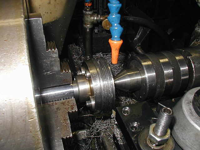
Photo #1 shows the serpentine belt held up to the pulley to see how things line up. Everything lined up perfect. Photo #2 shows the serpentine belt wrapped around the pulley like in operation. Photo #3 shows the completed pulley assembly. Next we'll work on the motor mounting...


12/18/04
Here in these next few photos, some cylinder work is being done on a 8 HP Evans engine. Photo #1 shows getting the frosty / cold cylinder up on the Lucas HBM. Photo #2 shows setting up the Sunnen hone to try to clean up the bore. Photo #3 shows starting to work on the bore...


Photos #1 & #2 show the bore starting to clean up. There is an area in the front of the cylinder that we are not worrying about as the piston and rings don't ride in that area. A lot of kerosene is used during honing to keep the stones clean and cutting. Photo #3 shows the completed bore with almost all the imperfections removed...


12/28/04
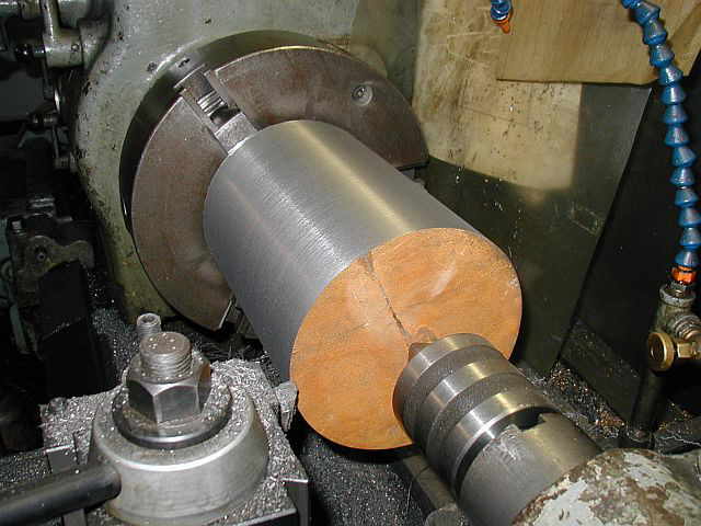
Well here in these next series of photos I'm starting to work on machining up the 8 HP Associated piston. This is for the 8 HP Associated cylinder I just bored. It's a new casting of a piston made from a pattern the fellow who owns the engine had made up. Photo #1 shows getting the piston setup on the Lucas HBM to machine the back end of the piston for mounting in the lathe later. Photo #2 is another view of the setup. Photos #3 & #4 show an original 8 HP Associated piston that I am using for reference. Notice the machine work on the back of the piston...


12/29/04
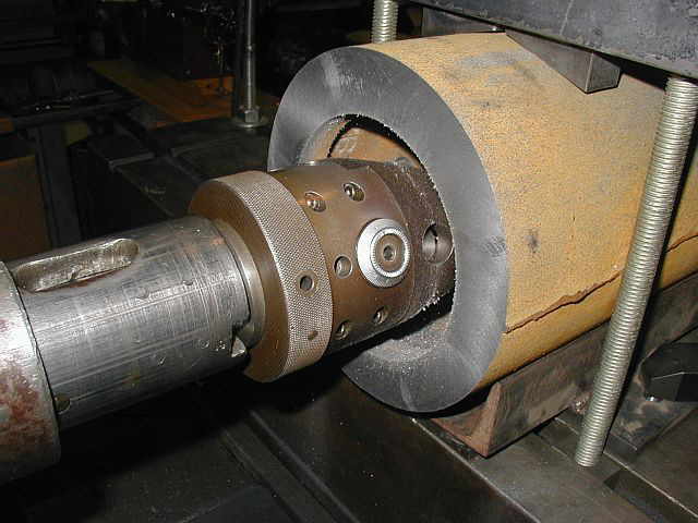
Here in these (3) photos I reconditioned the intake and exhaust valve seats in the 8 HP Evans head. Photo #1 shows the valve seats before reconditioning. Photo #2 shows a grinding stone dressed to the proper angle. Photo #3 shows the valve seats all ground and the valves lapped in. We should have good compression now...


Photo #1 shows the rear face of the piston starting to clean up. Photo #2 shows taking the last pass on the rear surface. Photo #3 shows the back surface completed...


While the piston was setup on the Lucas HBM I decided to drill and tap the wrist pin locking set screws. Photo #1 shows center drilling the first hole. Photo #2 shows the first hole drilled and tapped. Photo #3 shows the (2) holes completed with spot faces machined over each hole...


01/05/05
Here in these next few photos a .375 thick X .750 wide X 4.500 long strap is being fabricated to aid in getting the HBM machine spindle on center line with the piston casting. Photo #1 shows milling the strap to width. Photo #2 shows center drilling the (2) mounting holes and the actual center that will be for the piston. Photo #3 shows the holes and center drill all completed and de-burred...


Photo #1 shows the strap mounted to the piston. Notice the center drill in the center of the strap. This is the center of the piston. Photo #2 shows using a wiggler to get the HBM machine spindle on the center line of the piston casting. Photo #3 shows the boring head in the HBM machine spindle and being set up to bore the hole in the rear of the piston...


01/08/05 - 01/09/04
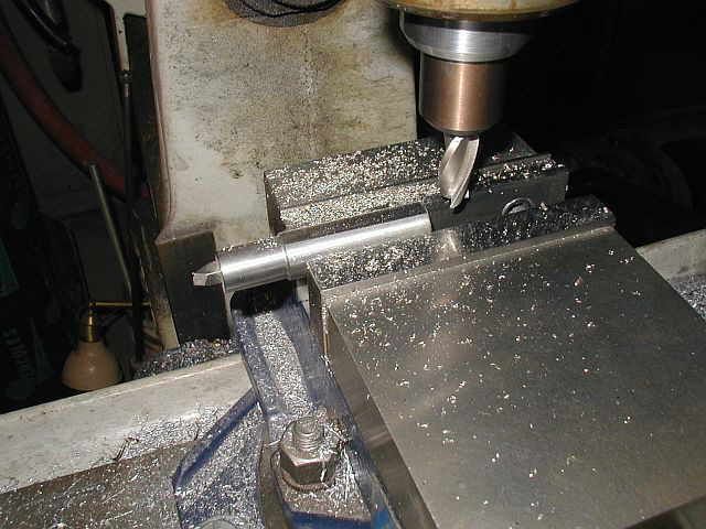
Here in these next few photos I started to make a special tool for the boring head. Photo #1 shows center drilling the toolholder. Photo #2 shows the hole drill for the tool bit and chamfered. Photo #3 shows center drilling a hole in the vertical mill...


Photo #1 shows tapping the hole for a set screw. This set screw will hold the tool bit in the toolholder. Photo #2 shows milling a flat on the toolholder in the vertical mill. This flat will be used for holding the toolholder in the boring head. Photo #3 shows the finished flat...


Here you can see the toolholder and tool bit in action. Photo #1 shows starting to bore the hole in the back of the piston. This bored hole and flat surface will be used to hold the piston in the lathe chuck for turning the OD and cutting the piston ring grooves. Photo #2 shows the bored hole starting to clean up. Photo #3 shows the finished hole...


In photo #1 you can see the piston in the lathe and center drilled. Photo #2 shows starting to turn the OD of the 8 HP Associated piston. Photo #3 shows the entire diameter cleaning up. Now to get the OD to the finished diameter...


Shop Work Continued on Page #33
Page 1, Page 2, Page 3, Page 4, Page 5, Page 6, Page 7, Page 8, Page 9, Page 10, Page 11, Page 12, Page 13,
Page 14, Page 15, Page 16, Page 17, Page 18, Page 19, Page 20, Page 21, Page 22, Page 23, Page 24, Page 25,
Page 26, Page 27, Page 28, Page 29, Page 30, Page 31, Page 32, Page 33, Page 34, Page 35, Page 36, Page 37,
Page 38, Page 39, Page 40, Page 41, Page 42, Page 43, Page 44, Page 45, Page 46, Page 47, Page 48, Page 49, Page 50,
for more Shop Work.
 |
Antique Gas Engine WebSite |
|
 Website designed and maintained by , Pavilion, NY.
Lunarpages Affiliate Program

Registered User #157284
Sun, Sparc, Ultra60 running Aurora 1.0 (RedHat Linux 7.3)
in mind, and are meant entirely for fun. No copyright infringements (if any) are done intentionally.