Shop Work Page #37

This webpage shows the current jobs
being worked on in the shop.
Hope you enjoy the activity.
Page 1, Page 2, Page 3, Page 4, Page 5, Page 6, Page 7, Page 8, Page 9, Page 10, Page 11, Page 12, Page 13,
Page 14, Page 15, Page 16, Page 17, Page 18, Page 19, Page 20, Page 21, Page 22, Page 23, Page 24, Page 25,
Page 26, Page 27, Page 28, Page 29, Page 30, Page 31, Page 32, Page 33, Page 34, Page 35, Page 36, Page 37,
Page 38, Page 39, Page 40, Page 41, Page 42, Page 43, Page 44, Page 45, Page 46, Page 47, Page 48, Page 49, Page 50,
for more Shop Work.
04/14/05 - 04/16/05
Not much antique engine activity in the shop taking place this past week. Time has been being spent getting the garden equipment ready for use. The (2) bottom plow needed repair a long with the 6' disc. These (2) photos show a carry all that I made years ago that needed a new floor / deck. Photo #1 shows cutting some 1/4" diamond plate for the new floor / deck. The second photo shows the completed floor / deck...


04/18/05 - 04/24/05
With the 10 HP Bessemer piston back from the metal spraying shop, the OD is turned to size and an oil groove cut. Photo #1 shows the oil groove being cut. Photos #2 & #3 show cutting the right hand side of each of the piston ring grooves. Notice the compressed air being used to keep the iron chips / dust out of the groove...


Photo #1 shows cutting the left side of the piston rings grooves. All the grooves will be cut to the same width using the compound slide. Photo #2 is an overall shot of the piston with all the ring grooves completed. Photo #3 is a close up of the ring grooves...


The next step is to figure out where to locate the piston ring keeper pins. Photo #1 shows drilling and tapping the keeper pin holes to a 1/4-20 thread. Photo #2 shows loc-tite applied to the screw threads and the screws tightened up. Photo #3 shows the keeper pins cut down below the surface of the piston OD. We're ready to order rings...


05/14/05 - 05/16/05
With the weather getting better, a lot of shop time has been spent repairing equipment for preparing the garden and for grass cutting. Seems like all this equipment always gets neglected. My youngest son Christopher is working on putting together a mini bike. He needed to make a bushing for an existing clutch he had so he went to work on the lathe. Here in these (2) photos you can see him drilling out the bushing...


For boring the 10 HP Superior cylinder I have decided to make a new boring bar / tool holder. Photo #1 shows a piece of 2.000" diameter O1, 6' long. Notice the #5 MT tool holder fit to the end of the bar. Photo #2 shows a flat being milled on one end of the new bar. Photo #3 shows the new boring bar in the machine. This should make for a nice stable boring bar...


A long with the new boring bar, a new outboard bearing needs to be fabricated. This will be a split bushing made out of phenolic. This photo shows starting to cut a piece of phenolic from a 5" thick block on the bandsaw...

Christopher is continuing his work on the bushing. Photo #1 shows reaming the ID to size. Photo #2 shows deburring the ID. Photo #3 shows one end of the bushing completed. Photo #4 shows drilling a hole in the bushing so a set screw can protrude through it and lock on the crankshaft. Photo #5 shows the bushing completed and inserted into the clutch...


Photo #1 shows more cutting on the phenolic block. Photo #2 shows a driver I made to bolt to the phenolic blank to hold it in the lathe. Photos #3 & #4 show drilling and tapping (2) holes to mount the driver to the phenolic blank. Photo #5 shows the driver all mounted to the phenolic blank ready to go into the lathe...


06/06/05 - 06/08/05
The work continues on making a new split bushing for the outboard bearing support. Photo #1 shows the OD of the phenolic bushing turned to size and tried in the outboard bearing block. Photo #2 shows the bushing turned around in the lathe and a 1.937 diameter hole drilled through the bushing. Photo #3 shows boring the hole to final size...


Photos #1 & #2 show cutting the bushing to length with the parting tool, leaving .030 for facing. Photo #3 shows facing the end and bringing the bushing to length. Photo #4 shows the new bushing with the lathe work completed, with chamfers and deburring done...


In the first photo, (4) drill points are being put in where the set screws will contact the bushing. Photo #2 shows the bushing being split on the bandsaw. Photo #3 shows the new bushing installed and ready for action...


06/20/05 - 06/21/05
The piston rings for the Bessemer cylinder project came in, so the final fitting was completed. In photo #1 you can see the piston ring in the new bore, setting the end gap. Photo #2 is a close/up of the piston ring end gap. Photo #3 shows how the hole for the keeper pin is machined into the piston ring. The clamping is not shown so you can see the piston ring. Photo #4 shows the (4) piston rings fitted and installed on the piston. This Bessemer cylinder is now ready for action...


07/05/05 - 07/06/05
This photo shows a small 10 Ton Enerpac cylinder I mounted to my press. This type of cylinder makes things a little more compact and still have the 10 Ton capacity...

In these next (4) photos you can see some work being done on a crankshaft. The keyway was originally machined off center and is causing the spokes to not line up. Also the original key was machined on a slight angle. Photo #1 shows setting the crankshaft up in the shaft vise on the vertical mill. Photo #2 shows indicating the crankshaft and getting it on center. Photo #3 shows taking the first pass on one side with photo #4 showing the finish pass on the opposite side. A special stepped key will have to be made now but the spokes will now line up...


07/08/05 - 07/09/05
Here in these next (3) photos you can see a Hercules ignitor that I am making plus rebuilding the original. Photo #1 shows facing the front side of the ignitor in the lathe. Photo #2 shows the facing completed. Photo #3 shows the original ignitor next to the new one starting to take shape...


07/10/05 - 07/11/05
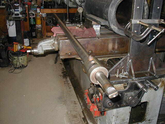
Well I have started doing some work on my 25 HP Columbus. In the next (4) photos you can see the sideshaft in the lathe getting cleaned up. There are a few items that need to be rebuilt on the cam end of the sideshaft. Overall the sideshaft is in good shape...


Photo #1 shows getting the rear sideshaft mount on the base cleaned and ready for the sideshaft bracket. A tap was run through the threaded holes to clean them up. Photo #2 shows the rear sideshaft bracket in place. Photo #3 is a front view of the rear bracket mounted to the engine base...


This photo shows my son Christopher helping out to clean and polish the sideshaft up in the lathe. It's taking quite a bit of elbow grease...

07/13/05 - 07/23/05
This is a photo of the tag on the 25 HP Columbus...

With the parts getting repaired and cleaned up, we're starting to assemble them. These next (3) photos show the sideshaft support brackets in place and the sideshaft installed. Also the governor assembly was mounted to see what it will look like on the engine. Some repair and cleaning still need to be done on the governor assembly...


These next (2) photos show cleaning up the head or cover plate for the engine. The Columbus is a headless engine, so it is just a cover plate for sealing the water jacket up. The first photo shows spinning the backside of the cover plate in the 3 jaw chuck. Photo #2 shows the cover plate mounted to a faceplate...


In these next (4) photos you can see a step key milled up for the above crankshaft that was repaired. Photo #1 shows indicating the vise in. Photo #2 shows milling down the key to the proper height. Photo #3 shows the width of the key milled to size and the step being cut in. Photo #4 is of the completed key...


07/25/05 - 07/28/05
Below is some ignitor work being done. Photo #1 & #2 show a new stationary point being trued up in the lathe. This is the stationary point that will be isolated from the engine...


In these next (3) photos you can see a small ground screw that was broke off in the ignitor housing being drilled out and the threads chased...


A new pivoting point needs to be fabricated and this photo shows the start of turning one in the lathe. The original pivoting point is worn out beyond repair...

Shop Work Continued on Page #38
Page 1, Page 2, Page 3, Page 4, Page 5, Page 6, Page 7, Page 8, Page 9, Page 10, Page 11, Page 12, Page 13,
Page 14, Page 15, Page 16, Page 17, Page 18, Page 19, Page 20, Page 21, Page 22, Page 23, Page 24, Page 25,
Page 26, Page 27, Page 28, Page 29, Page 30, Page 31, Page 32, Page 33, Page 34, Page 35, Page 36, Page 37,
Page 38, Page 39, Page 40, Page 41, Page 42, Page 43, Page 44, Page 45, Page 46, Page 47, Page 48, Page 49, Page 50,
for more Shop Work.
 |
Antique Gas Engine WebSite |
|
 Website designed and maintained by , Pavilion, NY.
Lunarpages Affiliate Program

Registered User #157284
Sun, Sparc, Ultra60 running Aurora 1.0 (RedHat Linux 7.3)
in mind, and are meant entirely for fun. No copyright infringements (if any) are done intentionally.