Shop Work Page #44

This webpage shows the current jobs
being worked on in the shop.
Hope you enjoy the activity.
Page 1, Page 2, Page 3, Page 4, Page 5, Page 6, Page 7, Page 8, Page 9, Page 10, Page 11, Page 12, Page 13,
Page 14, Page 15, Page 16, Page 17, Page 18, Page 19, Page 20, Page 21, Page 22, Page 23, Page 24, Page 25,
Page 26, Page 27, Page 28, Page 29, Page 30, Page 31, Page 32, Page 33, Page 34, Page 35, Page 36, Page 37,
Page 38, Page 39, Page 40, Page 41, Page 42, Page 43, Page 44, Page 45, Page 46, Page 47, Page 48, Page 49, Page 50,
for more Shop Work.
Shop Work Continued from Page #43
02/07/06 - 02/08/06
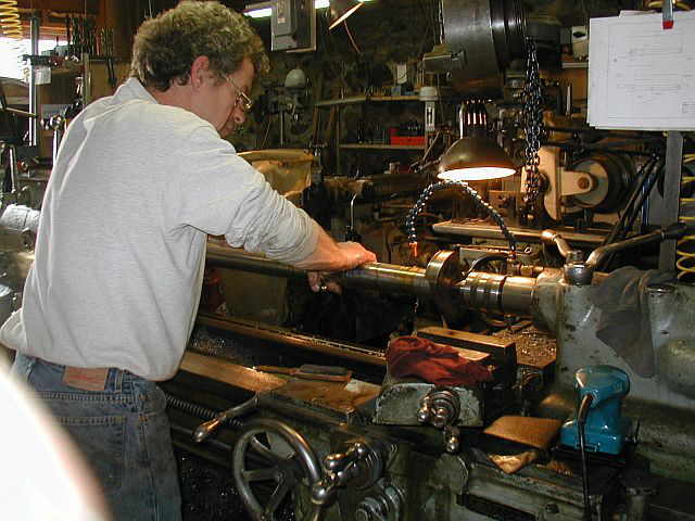
Here in these (3) photos you can see I have started making a new crosshead wrist pin. Photo #1 shows indicating the pin material in the (4) jaw chuck. Photo #2 shows center drilling the pin material. Photo #3 shows taking the first pass on the OD...


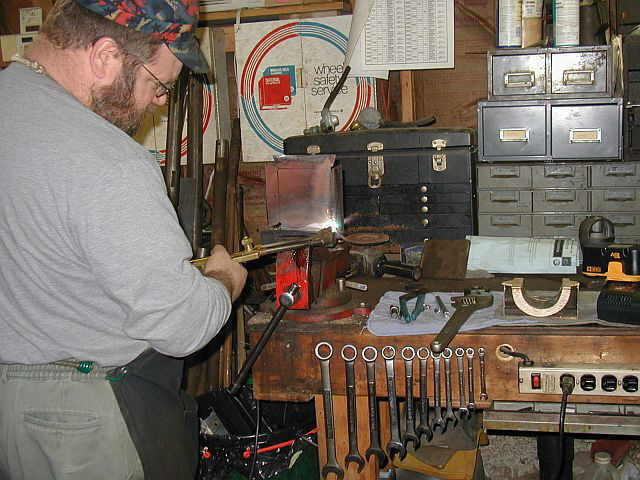
Had to switch gears and make a couple of parts for the snow plow. The parts we had to make are the shoes the plow rests on when in the down position. Photo #1 shows cutting the steel out on the bandsaw. Photo #2 shows Christopher drilling and de-burring (4) holes in each plate for bend relief. Photo #3 shows the corners cut out on the bandsaw...


Photo #1 shows heating up the 1/4" thick material on the bend line. Photo #2 shows the (2) shoes formed up and ready for welding...

02/09/06
In Photos #1 & #2 I am welding up the corners of the 1/4" thick plate. Photo #3 shows the first post welded to the shoe. The posts are made out of 1.125 diameter threaded rod so that I will have some initial adjustment on the height the shoe will hold the plow off the ground. Photo #4 shows all the welding completed...


Photo #1 shows drilling a hole for the cotter pin. Photo #2 shows what the new shoe looks like assembled on the plow...


These (2) photos show the plow in action with the new shoes installed. This should help keep the plow from digging into the stone driveway and prevent the plow edge from wearing out so fast...


02/11/06 - 02/12/06
In these (2) photos my son Christopher was doing an experiment for school which required heating up a piece of steel and quenching it in oil. Photo #1 is heating the old rail road spike up with the torch. Photo #2 is quenching it in oil...


Photo #1 shows turning the finished OD of the new crosshead wrist pin. Photo #2 shows rough cutting the pin to length in the power hacksaw...


Both ends of the new pin are faced. Photo #1 shows the facing of the first end. Photo #2 shows what the finished end looks like...


Next the new crosshead pin is setup in the shaft vise on the vertical mill. Photo #1 shows milling the first flat on the pin. This flat is where the locking set screw contacts the pin. Photo #2 shows milling the second flat. Photo #3 shows the completed pin assembled into the crooshead...


02/15/06 - 02/19/06
Have just received these (8) new piston rings and am getting ready to mill the keeper pin holes in the ring gap. Photos #2 & #3 show the setup...


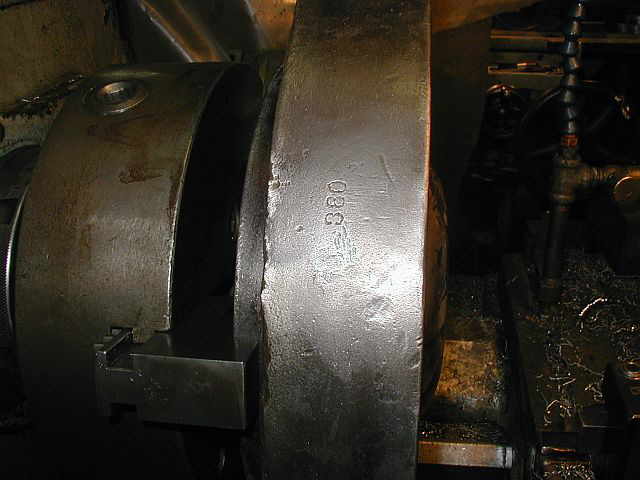
Doug Allen brought some parts over to the shop from a New Era he is restoring. These (4) photos show the head being mounted in the lathe and some passes being taken to clean things up. Photo #1 shows a number of 380 stamped in the head...


These (4) photos show more of the face being machined and then also the outside diameter of the head too...


Photo #1 shows Doug doing some hand work on the New Era head. Photo #2 shows the completed head. Boy it looks like new. Next Doug started on the New Era connecting rod. Photos #3 & #4 shows the connecting rod in the lathe and Doug starting to work on it...


Back to the International tractor rings. (4) are now completed and (4) to go. The third photo shows all (8) rings completed...


Photo #1 shows Doug putting the finishing touches on the connecting rod. Photos #2 & #3 show the completed connecting rod. Wow does it look nice...
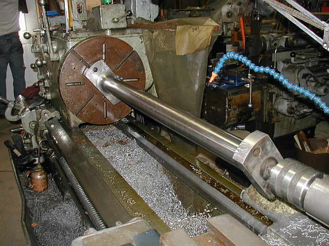

In these next (3) photos I am putting the tombstone on the Lucas HBM. I am getting set up to machine the (2) top crosshead rails for the 25 HP Swan engine. Photo #3 shows the crosshead rail bolted to the tombstone just for setting up the locators and checking spindle travel...


Not all work in the shop has to do with engine restorations and machining. Here in this photo my son Christopher is making a small table for his room. Looks good Chris...

02/21/06 - 02/26/06
Here in this photo you can see the tombstone being indicated. One of the crosshead top rails is mounted to the tomstone so machine table travels can be verified...

A holding fixture has to be built for machining the crosshead top rails. Photo #1 shows cutting the 3/4 X 4.00 wide stock on the power hacksaw. Photo #2 shows all the components cut and ready for deburring...


A pair of special screws needed to be made for the Swan crosshead bearing strap. Photo #1 shows a piece of hex stock in the lathe ready for turning. Photo #2 shows starting to turn the OD down to size. Photo #3 shows the OD turned down to size...


Photo #1 shows the thread cutting tool set up and the first few passes being made. Photos #2 & #3 show the finished threads. Photo #4 shows the (2) screws removed from the lathe with the head end needing to be cut to length...


These (2) photos show the screw heads being cut to length using a parting tool in the lathe...


Photo #1 shows using a radius tool bit to turn the crown on the screw head. Photo #2 shows the crowned screw head. Photo #3 shows the (2) screws completed. Photo #4 shows the (2) bearing strap screws and the (2) set screws and jam nuts that will hold the crooshead pin in place...


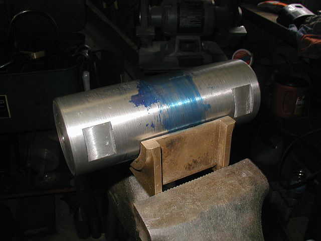
The first photo here shows the (2) set screws and jam nuts in place. Photo #2 shows the bearing halfs being fitted to the new crosshead pin. Prussian blue was used for finding the high areas on the bearing. Photo #3 shows the entire crosshead assembly completed...


Ron Polle came over the shop to work on a gib key puller. Photo #1 shows Ron drilling a hole in a piece of 3/4 thick plate in the lathe. Photo #2 shows Ron opening the hole up to 1 15/16 diameter. Photos #3 & #4 show Ron boring the hole to size...


Photo #1 shows drilling holes in the plates for the fixture that will hold the crosshead top rails. Photo #2 shows some of the plates completed...


02/28/06 - 03/05/06
In These next (2) photos work is continuing on the fixture for machining the crosshead top rails of the 25 HP Swan. Photo #1 shows cutting (12) pieces on the power hack saw to length. Photo #2 shows the stack of (12) pieces ready for deburring...


These are a couple of images that show the fixture design that I am building to mount to the tombstone for machining the crosshead top rails. These (2) images will give you an idea of what the fixture will look like...


With the deburring operation completed the next step was to drill a hole in all (12) details for the jack support screws. Photo #1 shows the setup used for drilling the .312 diameter hole. Photo #2 shows tapping the holes to a 3/8-16 thread. Photo #3 shows all the holes threaded and deburred...


Before welding, a 45 deg. chamfer was put on all (12) details, photo #1 shows this. Photo #2 shows one of the setups for welding one of the support assemblies. Photos #3 & #4 show the first assembly welded...


Photo #1 shows the second support assembly being welded. Photo #2 shows all the details welded up and deburred. The next step is to mount them onto the tombstone...


In photo #1 you can see the support brackets mounted on the tombstone. Photo #2 shows what it will look like with the crosshead top rail in the fixture. The crosshead rail is just resting on the lower supports...


Twelve jack support screws needed to be made. Photo #1 shows grinding a point on the end of a 3/8-16 SHCS. Photo #2 shows using the height gage to get the crosshead top rail positioned in the fixture...


These next (2) photos are of Ron's gib key puller that he was working on last week. (see above) In the photos notice the pocket milled out for locking / clearance onto the gib key tang. Ron has removed the gib key with his puller and he said it worked out great. Nice puller Ron. We all know how tough gib keys can be to remove...


With the crosshead top rail positioned in the fixture the tool is setup and the first pass taken. Photo #1 shows the first pass. Because of the length of the crosshead top rail and the machine table travel, the cut came in from the top and then across the rail and back up again. Photo #2 shows the first pass across the rail. Photo #3 is taken looking up at the crosshead rail from under the spindle...


Below is a small video clip (no sound) of taking a pass on the Swan crosshead top rail...

Swan crosshead top rail, Video Clip
Shop Work Continued on Page #45
Page 1, Page 2, Page 3, Page 4, Page 5, Page 6, Page 7, Page 8, Page 9, Page 10, Page 11, Page 12, Page 13,
Page 14, Page 15, Page 16, Page 17, Page 18, Page 19, Page 20, Page 21, Page 22, Page 23, Page 24, Page 25,
Page 26, Page 27, Page 28, Page 29, Page 30, Page 31, Page 32, Page 33, Page 34, Page 35, Page 36, Page 37,
Page 38, Page 39, Page 40, Page 41, Page 42, Page 43, Page 44, Page 45, Page 46, Page 47, Page 48, Page 49, Page 50,
for more Shop Work.
 |
Antique Gas Engine WebSite |
|
 Website designed and maintained by , Pavilion, NY.
Lunarpages Affiliate Program

Registered User #157284
Sun, Sparc, Ultra60 running Aurora 1.0 (RedHat Linux 7.3)
in mind, and are meant entirely for fun. No copyright infringements (if any) are done intentionally.