Shop Work Page #47

This webpage shows the current jobs
being worked on in the shop.
Hope you enjoy the activity.
Page 1, Page 2, Page 3, Page 4, Page 5, Page 6, Page 7, Page 8, Page 9, Page 10, Page 11, Page 12, Page 13,
Page 14, Page 15, Page 16, Page 17, Page 18, Page 19, Page 20, Page 21, Page 22, Page 23, Page 24, Page 25,
Page 26, Page 27, Page 28, Page 29, Page 30, Page 31, Page 32, Page 33, Page 34, Page 35, Page 36, Page 37,
Page 38, Page 39, Page 40, Page 41, Page 42, Page 43, Page 44, Page 45, Page 46, Page 47, Page 48, Page 49, Page 50,
for more Shop Work.
Shop Work Continued from Page #46
05/01/06 - 05/04/06
Here in this first photo I have started working on a Julian piston and connecting rod. This photo shows the wrist pin pulled out and things disassembled...

Photo #1 shows the piston set up in the lathe. Photo #2 shows drilling holes for the piston ring keeper pins. Photo #3 shows tapping the (4) keeper pin holes. Photo #4 shows the (4) keeper pins all installed...


The 10 HP Bovaird & Seyfang piston needs keeper pins too. Photo #1 shows the holes drilled in the ring grooves for the keeper pins. Photo #2 shows tapping the holes. Photo #3 shows the keeper pins all installed and ground to be below the surface of the OD on the piston...


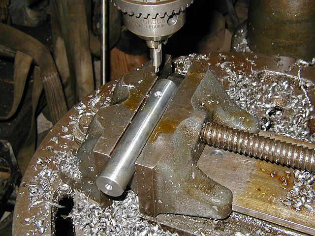
A new wrist pin needs to be fabricated for the Julian engine project. Photo #1 shows center drilling and facing one end of the new wrist pin. Photo #2 shows cutting the wrist pin to length in the power hacksaw. Photo #3 shows the wrist pin turned / faced to the new length and placed in the piston...


Photo #1 shows transfering the set screw locations from the piston to the wrist pin. Photo #2 shows center drilling the holes for the set screws. Photo #3 shows the completed wrist pin...


05/05/06 - 05/07/06
A new connecting rod bushing needs to be fabricated. Photo #1 shows a piece of bearing bronze in the lathe being center drilled and faced. Photo #2 shows the OD of the bushing being turned. Photo #3 shows the OD of the bushing completed...


Next the bushing is cut to length in the power hacksaw shown in Photo #1. Photos #2 & #3 show drilling a hole through the bushing. Photo #4 shows boring the ID of the bushing to size...


Photo #1 shows doing a little deburring in the lathe. Photo #2 shows the new connecting rod bushing on the new wrist pin. Photo #3 shows the bushing installed in the connecting rod. Photo #4 shows the wrist pin in the new bushing...


I have a new silicon carbide grinding wheel I wanted to mount on the tool grinder. I needed to make an adapter plate to drive the new wheel because the wheel diameter was 1" smaller then the original wheel. This photo shows the new grinding wheel on the arbor...

Photo #1 shows drilling a hole through the adapter plate in the lathe. Photo #2 shows the adapter faced and a counter bored hole for clearance of a boss on the existing driver plate. Photo #3 shows reaming the hole to fit the grinder arbor. Photo #4 shows the other side of the adapter plate faced and chamfered...


Next (2) holes are drilled and tapped in the side for locking the adapter plate to the grinder arbor. Photo #1 shows drilling the (2) holes. Photo #2 shows tapping the (2) holes. Photo #3 shows (2) holes laid out for drilling and counterboring. These (2) screw holes will be used to mount the adapter plate to the existing driver plate. Photo #4 shows drilling and counterboring the (2) holes...


Photo #1 shows the completed adapter plate. Photo #2 shows (2) holes drilled and tapped in the existing driver plate for mounting the new adapter plate to. Photo #3 shows the (2) plates assembled along with the set screws and brass pins on the side...


Photo #1 shows all the parts before assembling onto the grinder. Photo #2 shows the completed project. It's going to be nice having a fresh grinding wheel for sharpening the carbide tool bits...


05/09/06 - 05/14/06
Here in these next few photos I started making a fixture / tool to help hold and compress the piston rings for milling in the hole for the keeper pins. Photo #1 shows laying out the holes for the dowel pins. Photo #2 shows reaming the holes for the dowel pins. Photo #3 shows pressing in the dowel pins in the press...


Photo #1 shows drilling (2) holes for mounting the tool to the angle plate. (2) studs will go through these holes. Photo #2 shows drilling a hole that will be used for loading the piston ring in the Tool...


In the first photo you can see a piston ring in the fixture all clamped and ready for milling. Photo #2 shows the hole milled in the piston ring...


Photo #1 shows the first piston ring milled. Photo #2 shows all (4) piston rings machined with the keeper pin hole. Photo #3 shows all (4) piston rings installed on the piston...


In photo #1 you can see some threads that needed to be repaired. These are for the set screws that keep the wrist pin securly in the piston. Photo #2 shows the new wrist pin and connecting rod bushing all assembled. Photo #3 shows the completed Julian job...


With the 10 HP Bovaird & Seyfang cylinder bore completed photo #1 shows removing it from the Lucas HBM. Photo #2 shows putting a 6 HP International Famous cylinder up on the HBM. Photo #3 shows getting the Famous cylinder ready for measuring...


Am working on a engine job for a fellow in Tenn. He has a special or should I say old thread on the engine that he sent me the specs on and it measures to be a 11/16-9 thread. Not very common anymore. A test screw was cut to verify the threads. Photo #1 shows turning the OD of the screw to .684. Photo #2 shows the finished OD. Photo #3 shows setting up the thread cutting tool...


These next (3) photos are of cutting the thread...


These (2) photos are of the completed thread...


Photo #1 shows the screw being cut to length on the power hacksaw. Photo #2 shows welding a small piece of square stock onto the screw for hand turning into the threaded hole. Photo #3 shows the screw after welding. Photo #4 shows the completed test screw...


05/21/06
My friend Dave Yorks brought over his Callahan model for some minor tuning. It's alway fun to work on one of these models. A little ignitor work was done a long with some adjusting to the side shaft and support bearings. After all the work was complete we started up the Callahan model and after a little adjustment to the fuel needle valve and choke it was running real nice. We ran it for quite a while as we didn't want to shut it off. These are (3) photos of the model as we were working on it...


This next project involves building a fixture to do some milling on a 3" pipe, 90 deg. elbow. Photo #1 shows cutting the threads off of a 3" X 12" long pipe nipple for use on the fixture. Photo #2 shows truing up the end of the pipe in the lathe and chamfering...


Photo #1 shows welding the cut-off nipple to a fixture plate for mounting to the mill. Photos #2 & #3 show the nipple welded to the plate...


05/29/06 - 05/30/06
These (2) photos show getting a roller pump ready for rebuild. I purchased a rebuild kit and have all the parts ready for assembly when the kit gets here. This pump mounts to the PTO of a tractor...


Here I have started to repair a cylinder end that has a few cracks in it. Photo #1 shows "V"ing out the cracks in the housing. Photos #2 & #3 show the welds in the cracks. This welding process took quite a while because only a 1/2" of weld was done at a time till the iron cooled down...


The cylinder end housing was then put in the lathe after welding and the OD turned down to clean it up. This is in preparation of sweating a sleeve over the OD to hold everything together. Photo #2 shows the cleaned up OD..


Shop Work Continued on Page #48
Page 1, Page 2, Page 3, Page 4, Page 5, Page 6, Page 7, Page 8, Page 9, Page 10, Page 11, Page 12, Page 13,
Page 14, Page 15, Page 16, Page 17, Page 18, Page 19, Page 20, Page 21, Page 22, Page 23, Page 24, Page 25,
Page 26, Page 27, Page 28, Page 29, Page 30, Page 31, Page 32, Page 33, Page 34, Page 35, Page 36, Page 37,
Page 38, Page 39, Page 40, Page 41, Page 42, Page 43, Page 44, Page 45, Page 46, Page 47, Page 48, Page 49, Page 50,
for more Shop Work.
 |
Antique Gas Engine WebSite |
|
 Website designed and maintained by , Pavilion, NY.
Lunarpages Affiliate Program

Registered User #157284
Sun, Sparc, Ultra60 running Aurora 1.0 (RedHat Linux 7.3)
in mind, and are meant entirely for fun. No copyright infringements (if any) are done intentionally.