of the
25 HP Swan Restoration
Continued...
See
Page 1, Page 2, Page 3, Page 4, Page 5, Page 6, Page 7, Page 8, Page 9, Page 10,
for more of the 25 HP Swan Restoration project.


Here in these 3 photos I have removed all the damning material and in the first photo you can see how nice the pour came out. Notice that the shims touch the side shaft. This allowed me to pour both the upper and lower bearing halves in one pour. Also notice in the pictures that the side shaft is sooted up so the babbitt doesn't stick to it...


These are a couple of photos taken after everything is all cleaned up and the new babbitt bearings scraped and grooved for fit and oil...


Now I start prepairing for pouring the governor shaft housing bearing. In this photo I am cooking all the moisture out of the casting. A very important point when pouring babbitt. Have all the parts clean and hot enough to remove all the moisture. If there is any moisture present when you pour the molten babbitt the moisture turns instantly into steam and can blow things up sending hot babbitt everywhere...

A common site on this engine! There has been a lot of babbitt to pour for this engine. In this photo I just started heating up some babbitt for the governor shaft pour...

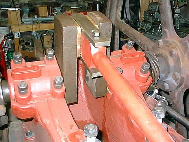
In the first photo here you can see the wood jig and the steel vee block I used for setting up the governor shaft. There were 2 tapered wedges used to hold another piece of wood up to the base of the governor housing. These are the 2 connecting rod tapered wedges used for taking up the bearing clearance. The second photo is after everything is taken apart and cleaned up, sanded, and fitted. If you have poured babbitt before you know the time it takes to setup for the pour and to clean up after the pour...


Well more of the governor parts are getting assemblied. In the second photo you can see the governor balls and some of the linkage installed...


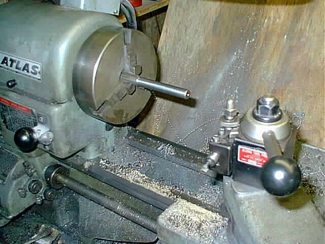
Next I needed to make 4 pins for the governor. I have reamed all the holes on the governor linkage and balls to .562 diameter and turned the pins to .558. This made a nice fit for everything to move freely...
Here is a photo of the governor assembly with all the linkage assemblied and setup. I don't have the governor drive gear on the side shaft in the proper location in this photo. I forgot to slide it forward before I took the picture. Well I am pretty happy with how the governor came out and can't wait to see it in action...

These 2 photos show the governor all assemblied with the counterbalance spring and adjuster installed. This makes the motion of the throttle plate very smooth and light to the touch. I am sure this will have to be fiddled with when the swan gets running...


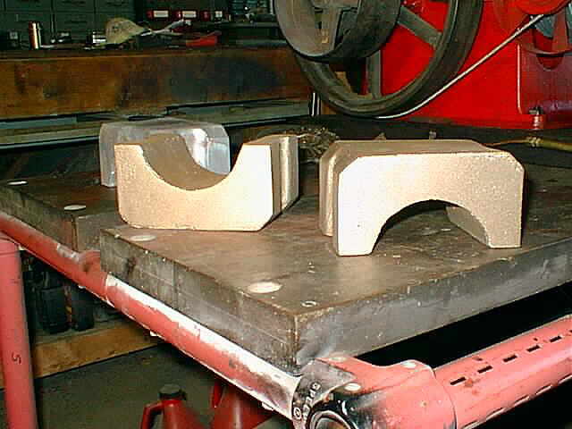
I got a call yesterday from the casting company that the 2 main bearing halves were done and ready for me to pick up. I got pretty excited over that news. Here in these photos you can see the pattern I made out of an old bearing half, wood, and fiberglass, and then the 2 new cast halves. These are the last parts needed to get the piston going back and forth. Now to start the machining on them...


To start the machining on the brasses I set them up in the shaper to true up the 2 inside surfaces of the bearing. This was done to both halves...

Next the brasses were set up in the vertical mill, located on the inside surfaces that were just trued up, and the back of the brasses were cleaned up with a fly-cutter. Now I have a couple of nice parallel surfaces to work with...

Now the brasses are in the lathe for boring and facing. Here in this photo I have just started boring the ID to 3.989. Notice the rough cast hole you have to start out with. There was about .300 material to remove on the radius...

In this photo you can see the bore completed and also the facing of one side. Next I need to chamfer the ID to make clearance for the radius on the crank shaft, then I will flip the brasses 180 deg. and face and chamfer the other side...

Here you can see the chamfer completed. Note the .090 shim between the 2 bearing halfs. This will provide clearance when the brasses are on the crank and adjusted with the wedge. You don't want the bearing halves to make contact when on the crank shaft ...

This is the setup I used for milling the slots in the brasses for sliding on to the bearing strap. In the first photo you can see the oil hole. The C-clamp was used here to help stabilize the brasses during machining. This bearing material really machined up nice...


The following are some photos of the bearings on the bearing strap. They fit real nice on the strap. Next will be to machine 2 more slots in the brasses opposite the 2 just machined in. One slot will be for the vertical side of the strap and the other will be for the wedge side that adjusts the bearing clearance...


In these 2 photos you can see the slot milled in the back of the bearing half. The bearing strap will be located in the slot to retain the bearing and hold the 2 halves together...


A 45 deg. angle was milled on the inside of the slot for clearance with the weld on the bearing strap. This was done on the upper and lower sides of the slot...

Here in these 2 photos you can see the brasses nested in the bearing strap with all the machining now completed. Now I will deburr the brasses and cut some oil grooves in to finish them up...


Well the engine is now one step closer to having the piston going in and out by turning the flywheels. Here in these 2 photos you can see the brasses and the bearing strap in place. I need to cut 2 rectangle slots and drill 2 holes in the bearing strap and the main connecting rod bearing assembly will be complete. Then I will be able to turn the flywheels over and move the piston...


Sha-zam! (05/20/99) The piston finally goes back and forth by turning the flywheels! For the Swan engine this has not been able to happen for 54 years, that the previous owner and I can tell. In these 2 photos you can see the 2 holes drilled for mounting the bearing strap to the connecting rod. I put in 1 bolt and turned the flywheels over and everything is working fine. What a feeling it is to be over this hurdle. Next I will cut the bearing strap to length and cut the rectangle slots for the wedge that will hold the bearings in place...

In these 2 photos I have completed the bearings and the strap. I milled the rectangle slots in both the upper and lower portions of the strap with a 5/16 diameter end-mill and filed the corners square. These are the slots where the tapered wedge goes through the strap. I just need to cut some oil grooves in the brasses and they will be ready for action...


Well the Swan starts to get some paint. I am painting the engine a dark green and am very happy with the color and the way the paint is going on. The color looks light in these photos, I think because I had a bright quartz light on along with the camera flash. The trim on the engine will be black. It will be a while before I get to that ...


See
Page 1, Page 2, Page 3, Page 4, Page 5, Page 6, Page 7, Page 8, Page 9, Page 10,
for more of the 25 HP Swan Restoration project.
 |
Antique Gas Engine WebSite |
|
 Website designed and maintained by , Pavilion, NY.
Lunarpages Affiliate Program

Registered User #157284
Sun, Sparc, Ultra60 running Aurora 1.0 (RedHat Linux 7.3)
in mind, and are meant entirely for fun. No copyright infringements (if any) are done intentionally.