Shop Work Page #1

This webpage shows the current jobs
being worked on in the shop.
Hope you enjoy the activity.
Page 1, Page 2, Page 3, Page 4, Page 5, Page 6, Page 7, Page 8, Page 9, Page 10, Page 11, Page 12, Page 13,
Page 14, Page 15, Page 16, Page 17, Page 18, Page 19, Page 20, Page 21, Page 22, Page 23, Page 24, Page 25,
Page 26, Page 27, Page 28, Page 29, Page 30, Page 31, Page 32, Page 33, Page 34, Page 35, Page 36, Page 37,
Page 38, Page 39, Page 40, Page 41, Page 42, Page 43, Page 44, Page 45, Page 46, Page 47, Page 48, Page 49, Page 50,
for more Shop Work.
Below you can see a few photos of a cylinder that I am getting ready to bore for a 5 HP Bovaird & Company, rare 2 cycle pumping engine. I will be posting photos here of the different work I will be doing in the shop.


These (2) photos are of making a boring tool to bore the above cylinder that is set-up on the Lucas Horizontal Boring Mill...


In these next (4) photos I made some axle stub shafts for a garden trailer. They were pressed and welded in place...


This is a piston for an 8 HP Pattin Brothers engine I had metal sprayed and turned down to the proper O.D. The rings grooves were also trued up. Notice the valve housing for a Bessemer engine next to the piston. I am pressing a bushing in for a new valve guide on that...

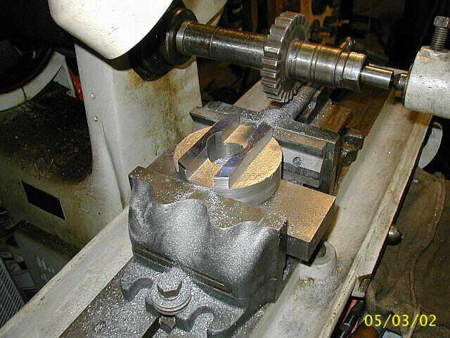
These next (3) photos are of a pulley being drilled and bored. and a hub being welded into the bore. This is going to be on a old Briggs & Stratton running an old compressor at the shows this year. Next I will turn a taper on the outside surface to simulate a crowned pulley...


These (2) photos are of a wrist pin for an 8 HP Pattin Brothers oil pumping engine...


In these next (4) photos you can see the taper attachment on the LeBlonde lathe being used to finish turning the O.D. of the pulley. The taper attachment worked out real well and if you look close at the pulley you can see the 3 deg. taper, starting in the center and working down towards the outside...


This photo shows the finished pulley and also a valve stem for a Bessemer flat intake valve I am making which I just finished cutting the 5/8-11 thread on...

Here in these (3) photos you can see the O.D. of the 4" boring tool taking shape. In photo #3 you can see the front faced off too...

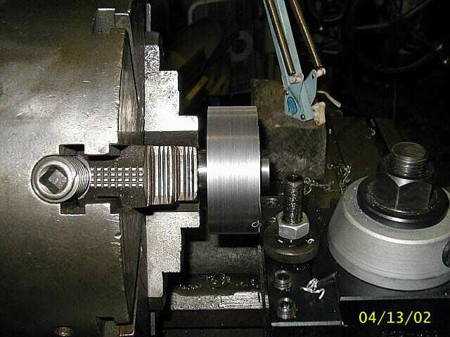

Photo #1 shows laying out the boring tool on the surface plate. Photo #2 shows indicating the vise to make sure its parallel to the table ways. Photos #3 & #4 show milling the boring tool. Notice I didn't wind up using the vise from photo #2. I wasn't happy with the way the tool was clamping up in the vise...


In these next (3) photos Ron Polle is working on a hub / spindle for a cooling fan for his 5 HP Bovaird & Company engine. Photo #1 shows the brass being turned down to the largest diameter needed. Photo #2 show some flanges starting to take shape. Photo #3 shows Ron hard at work...


Well, finally all the milling is done on the 4" boring tool...
Drilling a hole in the fan spindle...

These (2) photos are of more work on the Bessemer flat valve. Photo #1 is of the original Valve. If you look close you can see how badly worn the valve stem is. In photo #2 you can see a hole bored for a small stem hub in a round piece of .500 thick flat stock...


Photo #1 here is of a needle valve for a outboard motor. I needed to turn off the first 3 threads because they were stripped out. Photo #2 shows how the first 3 threads were removed from the main housing of the carburator using the drill press so the needle valve could be installed...


Here in these next (3) photos Ron Polle is finishing up the fan hub / spindle. In photo #1 Ron is finishing up drilling a 3/4" diameter hole in the hub / spindle. Photo #2 show the spindle being cut-off to length from the main piece of brass. Photo #3 shows Ron in the small Atlas lathe facing and chamfering each end of the hub / spindle...


This photo shows a couple of parts I had cut out on a wire EDM machine at work. One part is the latch dog for holding the exhaust valve open and the other part is the governor weight. Also shown in the photo is the hub / spindle for the fan. All these parts are for Ron Polle's 5 HP Bovaird & Company vertical...

These (2) photos are of facing a couple of 1986 Dodge pick/up truck front rotors...


In these (2) photos you can see a bushing / hub being made for the Bessemer flat valve. In photo #1 I just finished turning the OD of the bushing and drilling a 5/8" diameter hole for the valve stem. Photo #2 shows cutting the bushing / hub off of the parent material with the cut off tool. Notice the small head / shoulder left on the bushing / hub for pressing the bushing up against on the flat valve...


Photo #1 shows pressing the bushing / hub into the flat valve. Photo #2 is of the bushing / hub welded in place. Photo #3 shows turning the OD of the flat valve. The final diameter and thickness of the flat valve will be completed after the valve stem is welded into the bushing / hub. Turning the flat valve from the valve stem will make everything concentric and perpendicular to the center line...


In these next (4) photos you can see different stages of turning the intake valve and see it take shape. Photo #3 shows and undercut on the inside face of the valve. Just the exterior part of the valve will be ground, where the valve has to seal the gas off. Photo #4 shows the completed valve ready for grinding...


Now we move to another lathe and set the toolpost grinder up to grind the valve. In photo #1 you can see the set/up used for grinding the inside face of the intake valve. In photo #2 you can see the outside face all ground...


Page 1, Page 2, Page 3, Page 4, Page 5, Page 6, Page 7, Page 8, Page 9, Page 10, Page 11, Page 12, Page 13,
Page 14, Page 15, Page 16, Page 17, Page 18, Page 19, Page 20, Page 21, Page 22, Page 23, Page 24, Page 25,
Page 26, Page 27, Page 28, Page 29, Page 30, Page 31, Page 32, Page 33, Page 34, Page 35, Page 36, Page 37,
Page 38, Page 39, Page 40, Page 41, Page 42, Page 43, Page 44, Page 45, Page 46, Page 47, Page 48, Page 49, Page 50,
for more Shop Work.
 |
Antique Gas Engine WebSite |
|
 Website designed and maintained by , Pavilion, NY.
Lunarpages Affiliate Program

Registered User #157284
Sun, Sparc, Ultra60 running Aurora 1.0 (RedHat Linux 7.3)
in mind, and are meant entirely for fun. No copyright infringements (if any) are done intentionally.