Shop Work Page #10

This webpage shows the current jobs
being worked on in the shop.
Hope you enjoy the activity.
Page 1, Page 2, Page 3, Page 4, Page 5, Page 6, Page 7, Page 8, Page 9, Page 10, Page 11, Page 12, Page 13,
Page 14, Page 15, Page 16, Page 17, Page 18, Page 19, Page 20, Page 21, Page 22, Page 23, Page 24, Page 25,
Page 26, Page 27, Page 28, Page 29, Page 30, Page 31, Page 32, Page 33, Page 34, Page 35, Page 36, Page 37,
Page 38, Page 39, Page 40, Page 41, Page 42, Page 43, Page 44, Page 45, Page 46, Page 47, Page 48, Page 49, Page 50,
for more Shop Work.
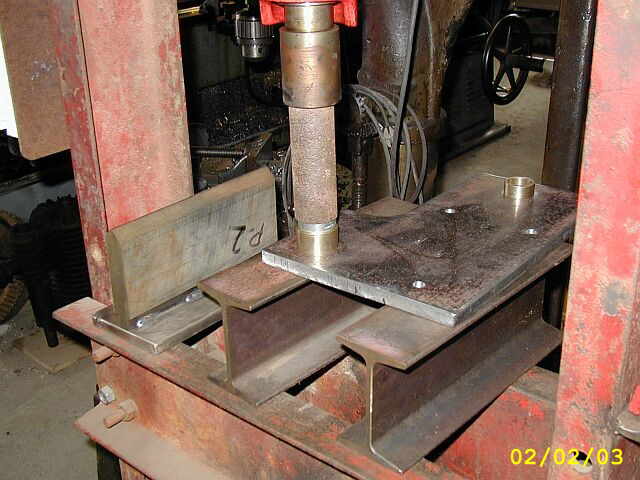
Photo #1 here shows the first bored hole completed for pressing in the lead screw support bushing. Photo #2 shows drilling the last and final hole to be bored. This hole is for the main drive shaft. In photo #3 you can see some clamping I added for stabilizing the plate where I am hanging out quite a bit...


In these first (3) photos Ron Polle is helping me by making a bushing that will be pressed into the plate for supporting the lead screw. Photo #4 shows an assembly drawing of what the Lucas Drive System is going to look like. Photo #5 shows the bushing on the lead screw...


Photo #1 here shows boring the hole for the drive shaft support bushing. Photo #2 shows the completed bored hole. Photo #3 shows the lead screw support bushing pressed into the plate...


The first (3) photos here show making the drive shaft support bushing with photo #3 showing the bushing on the drive shaft. Photo #4 is of pressing the drive shaft bushing into the main plate. Photo #5 shows the main plate all mounted on the Lucas Horizontal Boring Mill. I transfered the mounting holes from the main plate and then drilled and tapped them for a 3/8-16 socket head cap screw. Also in the photo you can see the drive adapter for the 10 tooth sprocket in place...


In photo #1 I have the 30 tooth sprocket in the lathe and am drilling the hole in the center. The original hole diameter in the sprocket was .375. Photo #2 shows boring the hole to .957. Photo #3 shows the 30 tooth sprocket after I drilled and tapped for (2) 5/16-18 set screws. This sprocket will get attached to the lead screw on the Lucas Horizontal Boring Mill..


Here I am starting to make the idler sprocket assembly. In Photo #1 I am drilling a hole in the center of the 10 tooth sprocket. In photo #2 I am facing off the 23 tooth sprocket to achieve a specific chain center line distance between the (2) sprockets. Photo #3 shows the (2) sprockets MIG welded together. Photo #4 shows reaming the ID of both sprockets after they are welded together...


With the sprocket assembly completed I can now finish turning the idler shaft that the sprocket assembly rides on. In photo #1 I am turning down the shaft and leaving a step to act as a shoulder for the sprocket assembly to ride against. Photo #2 shows the completed idler shaft. Photo #3 shows the sprocket assembly, washer, and screw all assembled and ready for action...


In these next (4) photos I am making a plate that the idler shaft gets pressed into and welded. Photo #1 shows cutting the plate to size. Photo #2 shows laying out the hole pattern on the surface plate. Photo #3 shows drilling the holes in the vertical mill and photo #4 shows the plate completed and the idler shaft assembly pressed in place. Now it needs to be welded...


Photo #1 here shows the idler shaft welded in place. In photo #2 I chucked the idler shaft in the lathe and refaced the back side of the idler plate to true it up. Photo #3 shows the 10 tooth sprocket all bored out to fit the adapter drive and pined in place. Photo #4 shows what the Lucas drive system is starting to look like now that some of the parts are being completed...


In these next (3) photos you can see the Lucas drive system being assembled. The idler shaft assembly is clamped in location because the (4) mounting holes need to be transferred to the main plate once the chains are in place and the proper tension acheived. In the last photo here the system is actually being run to see how it works. It really works great!...


On Saturday February 8th, I went over to my friend Dave Johnson's shop and helped him pour the babbitt for the main bearing on the connecting rod, for his 15 HP Titusville Olin restoration. Photo #1 shows heating up the babbitt. Photo #2 shows part of the setup used to line everything up. Photo #3 shows sooting up the crankshaft journal so the babbitt won't stick to it...


Photo #1 shows Dave putting some daming material around the brasses so the babbitt can't leak out during the pour. Photo #2 shows everything all ready for the pour. All the moisture has been cooked out of the setup and its all been sealed up. Photo #3 was taken right after the pour. No leaks! Photo #4 shows the (2) brasses after we disassembled the setup. We naturally had to let things cool for about 1/2 hour before we did this. Now after a little clean up the bearings will be as good as new...


Back to work on the Lucas drive system. We are getting real close to having it all completed. In photo #1 I have transferred the idler plate mounting holes and am drilling them in the vertical mill. They will also be tapped for a 5/16-18 thread. Here it is in photo #2, the completed Lucas drive system. It works great! This will allow boring of cylinders that are longer then the stroke of the spindle travel. The current cylinder I have on the Lucas is for a 15 HP International Famous and this new drive sustem will be used for that boring job. Reference photo #3 to see the cylinder on the Lucas...


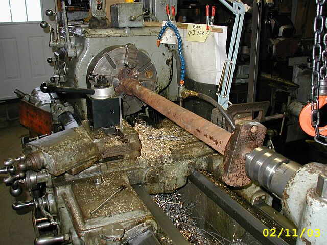
These next (5) photos show a job I did quick for a friend who is restoring an 18 HP Electric Lighting Buffalo Olin. One end of the connecting rod was rusted so bad, that a lot of the original material was just plain rusted away. In photo #1 the connecting rod is setup in the lathe. In photo #2 you can see how bad the surface where the brass bearing mounts is pitted. In photo #3 I sanded an area so I could get a smooth reading on the dial indicator so I could true up the connecting rod. Photo #4 shows how uneven the flange was rusted away. Photo #5 shows the flange all cleaned up and perpendicular to the center line of the connecting rod...


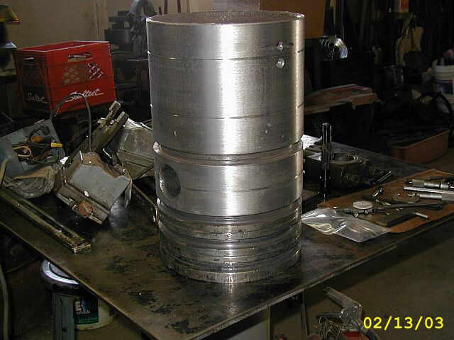
I got a call the other day saying the (2) pistons I had metal sprayed we done. I went and picked them up and am real happy how they turned out. In photo #1 you can see the piston for the 3 HP Pohl diesel engine. Photo #2 shows the piston for a 18 HP Buffalo Olin...

This is a photo of the finished connecting rod for the 18 Hp Buffalo Olin...

In these next (2) photos you can see the 3 HP Pohl connecting rod. Photo #1 shows the wrist pin bushing, and after measuring it and the wrist pin diameter they are in great shape. Photo #2 shows the wrist pin in the connecting rod bushing...
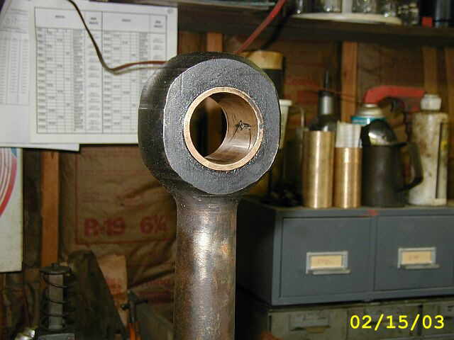

Photo #1 here shows the existing bore of the 15 HP International Famous cylinder. The photo was taken from the back end of the cylinder. If you look up towards the head end of the cylinder you can see how bad the bore has been pitted and rotted out from where junk sat and ate it away. Photo #2 shows indicating around the back ring just to get the cylinder close to where it should be located for boring. Photo #3 shows indicating the existing bore of the Famous cylinder to get it lined up with the machine spindle and platen...


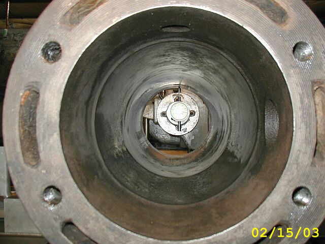
Photo #1 shows the boring tool mounted on the machine spindle and getting set up to make the first roughing pass. In photo #2, if you look close at the bore you can see the first roughing pass being fead slow and removing quite a bit of material to get under the rust and pitting. Photos #3 & #4 are from the head end looking at the actual carbide cutting tool in action during the first roughing pass...


Shop Work Continued on Page #11
Page 1, Page 2, Page 3, Page 4, Page 5, Page 6, Page 7, Page 8, Page 9, Page 10, Page 11, Page 12, Page 13,
Page 14, Page 15, Page 16, Page 17, Page 18, Page 19, Page 20, Page 21, Page 22, Page 23, Page 24, Page 25,
Page 26, Page 27, Page 28, Page 29, Page 30, Page 31, Page 32, Page 33, Page 34, Page 35, Page 36, Page 37,
Page 38, Page 39, Page 40, Page 41, Page 42, Page 43, Page 44, Page 45, Page 46, Page 47, Page 48, Page 49, Page 50,
for more Shop Work.
 |
Antique Gas Engine WebSite |
|
 Website designed and maintained by , Pavilion, NY.
Lunarpages Affiliate Program

Registered User #157284
Sun, Sparc, Ultra60 running Aurora 1.0 (RedHat Linux 7.3)
in mind, and are meant entirely for fun. No copyright infringements (if any) are done intentionally.