Shop Work Page #19

This webpage shows the current jobs
being worked on in the shop.
Hope you enjoy the activity.
Page 1, Page 2, Page 3, Page 4, Page 5, Page 6, Page 7, Page 8, Page 9, Page 10, Page 11, Page 12, Page 13,
Page 14, Page 15, Page 16, Page 17, Page 18, Page 19, Page 20, Page 21, Page 22, Page 23, Page 24, Page 25,
Page 26, Page 27, Page 28, Page 29, Page 30, Page 31, Page 32, Page 33, Page 34, Page 35, Page 36, Page 37,
Page 38, Page 39, Page 40, Page 41, Page 42, Page 43, Page 44, Page 45, Page 46, Page 47, Page 48, Page 49, Page 50,
for more Shop Work.
02/23/04
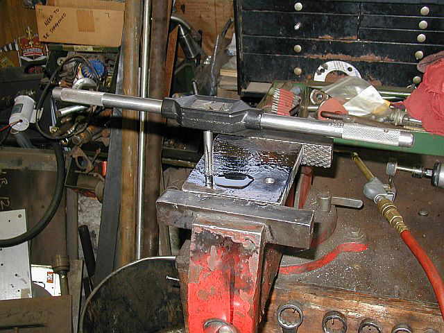
In these next (4) photos you can see the intake valve and seat being lapped in. Photo #1 shows how I rotated the intake valve. Photo #2 shows the lapping compound and what the seat is looking like. Photo #3 shows the completed intake valve face and seat all lapped. Photo #4 shows the intake valve assembly all completed and ready for action...


02/24/04
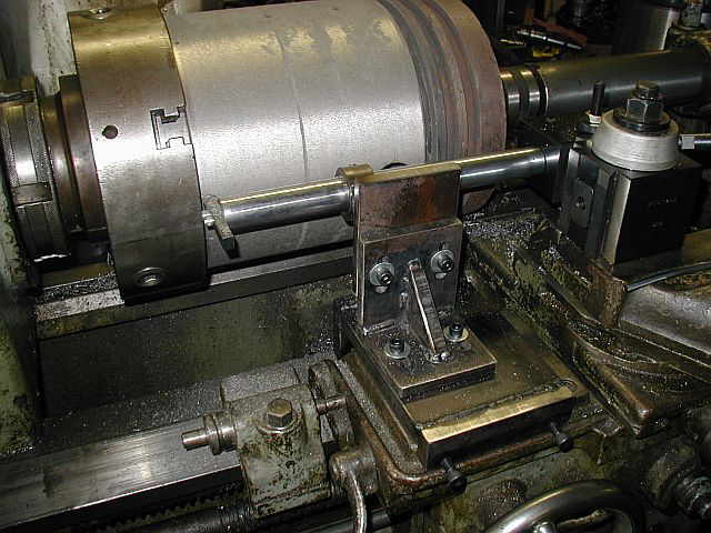
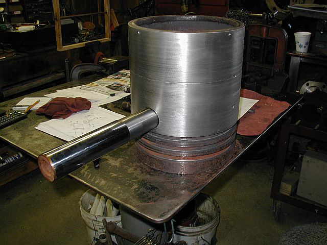
These (2) photos show putting the 22 HP Witte piston in the lathe. I'll be turning the OD of the piston to fit the new bore and then truing up the (3) ring grooves...


02/25/04
For turning the OD of the 22 HP Witte piston I need to make a special toolholder plus a tool support. Here in these next (4) photos you can see the design I whipped up for the tool support. Photo #1 is of the entire assembly and the next (3) photos are of the different assemblies that make up the tool support...


02/26/04
The first thing I made was the special tooholder. In photo #1 you can see (2) 1/4-20 holes being tapped. The second photo shows a modified insert toolholder attached to the 1 1/4 diameter shaft...


These next (4) photos are of making the tool support holder. Photos #1 & #2 show cutting 1/2 thick plate on the DoAll bandsaw. Photo #3 shows what one of the vertical weldments will look like. Photo #4 shows cutting a piece of round stock which will be welded to the vertical plate to stabilize the toolholder...


02/27/04
The first (2) photos show drilling & tapping (2) holes in the collar that will fit over the toolholder. Photo #3 shows cutting the 3/4" thick plate on the DoAll bandsaw which cuts it like butter. In the 4th photo, I put some of the cut pieces on the lathe so you can see what the tool support is going to look like. Photo #5 shows all the individual parts all cut and ready for de-burring...


02/28/04
This photo is of the Braden half breed project. I removed the five studs and had to use a little heat to break them free. If you look close in the photo at 6:00, you can see one of the studs that was broken off a long time ago. That will need to be removed. Also, there is a couple of cracks in the same area that need to be repaired...

The work continues on the tool support. In photo #1, I am drilling a hole at the end of each slot and then in photos #2 & #3 you can see Ron Polle milling the rest of the slot out. Photo #4 shows drilling and tapping a couple of holes in the other plates. Photo #5 is of the SHCS screws that will attach the main mounting plate to the LeBlond lathe. I ground these SHCS to a point with a 4 1/2" angle grinder. (4) will be used to mount the main plate to the lathe without haveing to drill and tap any holes in the lathe. In photo #6 you can see that the welding for the tool support is starting...


The first photo here shows the main mounting plate in place on the lathe. (notice the (4) pinch screws) Photo #2 shows the angle plate all welded up and photo #3 shows the angle plate mounted to the main plate...


02/29/04
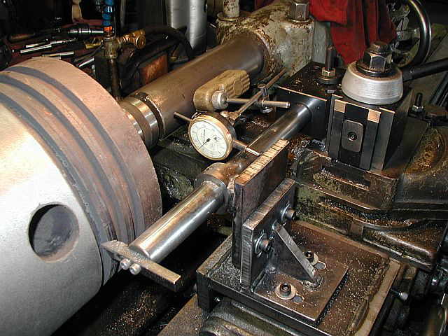
In the first photo here, the tool support is completed, all setup, and ready for action. When I need to index the cutting tool in, the (2) angle plate mounting screws need to be loosened up and then re-tightened, after the move. Photo#2 shows an indicator now part of the setup so I can insure how much the tool indexes in. Photo #3 shows one of the turning passes being taken, and photo #4 is of the piston with the OD now completed at 10.773...


These first (2) photos are interesting. They show the ring grooves and how badly worn they were. The original rings really hammered away in the grooves. Notice the step in the first ring groove in photo #1. Photo #2 shows the grooves all trued up and need just a little more clean up. Photo #3 is of the completed piston...


03/01/04
In photo #1 I have started to make a new wrist pin for the 22 HP Witte. Photo #2 shows the finish pass on the OD of the wrist pin. Photo #3 shows the wrist pin fit to the piston...


03/02/04
In Photo #1 the Braden cylinder gets put on the cart and prepaired for some welding. Photos #2 & #3 show holes drilled at the end of the cracks and the cracks all V'd out and ready for cleaning. In photo #4 the cracks are welded and in the area of where the head gasket goes, the welds are ground down. When the cylinder is set up in the Horizontal Boring Mill, a cleanup pass will be taken on the head gasket surface. Also notice that I have drill a 1/2" diameter hole in the broken off stud for removal...


Photo #1 shows running a 3/4-10 tap through the (6) holes where the studs go, for mounting the head. Photo #2 shows the broken off stud removed...


The Braden cylinder gets put up on the Lucas Horizontal Boring Mill. Now to get the cylinder located and secured to the machine table...


Shop Work Continued on Page #20
Page 1, Page 2, Page 3, Page 4, Page 5, Page 6, Page 7, Page 8, Page 9, Page 10, Page 11, Page 12, Page 13,
Page 14, Page 15, Page 16, Page 17, Page 18, Page 19, Page 20, Page 21, Page 22, Page 23, Page 24, Page 25,
Page 26, Page 27, Page 28, Page 29, Page 30, Page 31, Page 32, Page 33, Page 34, Page 35, Page 36, Page 37,
Page 38, Page 39, Page 40, Page 41, Page 42, Page 43, Page 44, Page 45, Page 46, Page 47, Page 48, Page 49, Page 50,
for more Shop Work.
 |
Antique Gas Engine WebSite |
|
 Website designed and maintained by , Pavilion, NY.
Lunarpages Affiliate Program

Registered User #157284
Sun, Sparc, Ultra60 running Aurora 1.0 (RedHat Linux 7.3)
in mind, and are meant entirely for fun. No copyright infringements (if any) are done intentionally.