Shop Work Page #13

This webpage shows the current jobs
being worked on in the shop.
Hope you enjoy the activity.
Page 1, Page 2, Page 3, Page 4, Page 5, Page 6, Page 7, Page 8, Page 9, Page 10, Page 11, Page 12, Page 13,
Page 14, Page 15, Page 16, Page 17, Page 18, Page 19, Page 20, Page 21, Page 22, Page 23, Page 24, Page 25,
Page 26, Page 27, Page 28, Page 29, Page 30, Page 31, Page 32, Page 33, Page 34, Page 35, Page 36, Page 37,
Page 38, Page 39, Page 40, Page 41, Page 42, Page 43, Page 44, Page 45, Page 46, Page 47, Page 48, Page 49, Page 50,
for more Shop Work.
04/04/03
Work is continuing on the 3 1/2 HP Fuller Johnson. Photo #1 shows positioning the mill using a wobber, to drill the cross hole in the wrist pin which will keep it locked into the piston. Photo #2 shows drilling the hole and photo #3 shows the finished wrist pin. In photos #4 & #5, a pin is being made to locate the connecting rod in the vertical mill. This was done to get the proper orientation of the connecting rod so the wrist pin bushing can be bored to size...


04/05/03
Photo #1 shows the set up used to locate and clamp the connecting rod. Photo #2 shows indicating the bushing ID to get it on center with the spindle. Photo #3 shows the boring being done. Photo #4 shows the wrist pin in the bushing. Photo #5 shows the completed bushing. Photo #6 shows the oil hole drilled and (2) oil grooves cut in with a dremel tool. Photo #7 shows the wrist pin fitted to the bushing and photo #8 shows everything all assembled...


04/06/03
In these first (4) photos work is continuing on some parts for the 60 HP Flickenger engine. Photo #1 shows the corliss box mounted on the Lucas horizontal boring mill table. Photos #2 & #3 show getting one of the old brass bushings out of the corliss box. We used a puller and then tapped on it with a hammer to shock it. Photo #4 is of the shaft that goes through the corliss box to operate the corliss valve. Photo #5 is of my son Christopher drilling some holes in a angle bracket for a school project. Photos #6 & #7 show Ron Polle doing some milling on a governor weight he is making for a 5 HP Bovaird & Company vertcal he owns. Photos #8 & #9 are close ups of the milling operation...


04/10/03
Photo #1 shows indicating the corliss box to get it lined up. Photo #2 shows a 1 1/2" diameter bar that will be used as a boring bar. There are (2) brass bushings that need to be pressed into each end of the corliss box. The shaft in front of the corliss box is the actual shaft that goes through the box. Photo #3 shows locating the hole that will have a toolbit in it for boring. Notice the hole is off center to bring the cutting edge of the toolbit to the center line of the bar. Photo #4 shows center drilling the hole, and photo #5 shows drilling the hole to 7/16" diameter. Photo #6 shows tapping a hole for a 1/4" set screw which will lock the toolbit in place. Photo #7 shows the completed bar...


04/11/03
In photo #1 the spindle of the Lucas horizontal boring mill is being positioned on center with the corliss box. Photo #2 shows the entire setup and the first pass being completed. Photo #3 shows material being removed during the first pass through the corliss box...


04/19/03
On 04/19/03 Mike Fuoco came over my shop to help out on getting the (3) sideshafts completed for the 60 HP Flickinger Compressor Engine. In the next (14) photos you can see some of the work we completed on the sideshafts and also the governor. While all this work was going on we still managed to make a few more passes through the corliss box with the boring bar on the Lucas Horizontal Mill. Hope you enjoy the photos. You will see everything from setting the vertical mill up for boring the governor housing, sanding and polishing the sideshafts in the lathe, milling the keyway slots, and reaming the governor belt pulley...


04/20/03
My friend Stiles Bradley has been working on the restoration of a 18 HP Electric Lighting Buffalo Olin. He finished putting the paint on and in these next (3) photos you can see how the paint job came out. It really looks awesome. The head in the photos is the one Stiles made in some previous photos here on the shopwork webpages...


These (2) photos are of a skid Stiles and I are building for the 20 HP Abel Acme engine restoration that I currently have going on, along with everything else. I need to make (3) cross pieces and then the Abel Acme bed plate can be mounted on the skid...
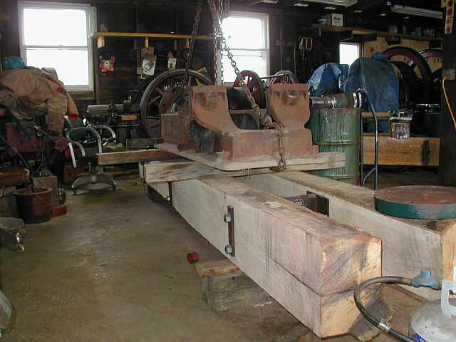

04/26/03
Below more work is continuing on the 20 HP Abel Acme engine skid. The photos below show cutting the cross bunks, cutting the plates to be welded onto the treaded rods, drilling the holes, routing pockets in the underside to except the threaded rod and plates. There are photos of rolling the heavy skid over after routing the pockets and then lowering the engine bed plate onto the skid. The last photo shows what the completed skid and engine bed plate look like together...


Shop Work Continued on Page #14
Page 1, Page 2, Page 3, Page 4, Page 5, Page 6, Page 7, Page 8, Page 9, Page 10, Page 11, Page 12, Page 13,
Page 14, Page 15, Page 16, Page 17, Page 18, Page 19, Page 20, Page 21, Page 22, Page 23, Page 24, Page 25,
Page 26, Page 27, Page 28, Page 29, Page 30, Page 31, Page 32, Page 33, Page 34, Page 35, Page 36, Page 37,
Page 38, Page 39, Page 40, Page 41, Page 42, Page 43, Page 44, Page 45, Page 46, Page 47, Page 48, Page 49, Page 50,
for more Shop Work.
 |
Antique Gas Engine WebSite |
|
 Website designed and maintained by , Pavilion, NY.
Lunarpages Affiliate Program

Registered User #157284
Sun, Sparc, Ultra60 running Aurora 1.0 (RedHat Linux 7.3)
in mind, and are meant entirely for fun. No copyright infringements (if any) are done intentionally.