Shop Work Page #36

This webpage shows the current jobs
being worked on in the shop.
Hope you enjoy the activity.
Page 1, Page 2, Page 3, Page 4, Page 5, Page 6, Page 7, Page 8, Page 9, Page 10, Page 11, Page 12, Page 13,
Page 14, Page 15, Page 16, Page 17, Page 18, Page 19, Page 20, Page 21, Page 22, Page 23, Page 24, Page 25,
Page 26, Page 27, Page 28, Page 29, Page 30, Page 31, Page 32, Page 33, Page 34, Page 35, Page 36, Page 37,
Page 38, Page 39, Page 40, Page 41, Page 42, Page 43, Page 44, Page 45, Page 46, Page 47, Page 48, Page 49, Page 50,
for more Shop Work.
03/18/05 - 03/20/05
Here in these next (4) photos the final passes are taken on the parallels to true them up on the shaper. Photo #1 shows the surface to be cut, blued up. Photo #2 shows the final pass almost completed on the first side. Photo #3 shows the first side all completed. Photo #4 shows the completed parallels. Can't wait to start using them. The first job I am going to be using them on is the 10 HP Bessemer cylinder bore job...


Before setting up the 10 HP Bessemer cylinder for boring, a crack must be repaired. I always try to have all the welding done on a cylinder before boring, not after. Photo #1 shows the crack on the bottom of the water jacket. Photo #2 shows how nice and clean the owner, Arnie Fero has the inside of the water jacket cleaned out. This is a must, as water soaked rust/lime can freeze and recrack the cylinder. It's hard to see in photo #3 but there are actually (2) cracks and I have drilled (4) holes, (1) at each end of the cracks to stop the crack from continuing. Using the die grinder with a small abrasive wheel and a carbide burr bit, a wide deep "V" groove is cut over the crack. The groove can be seen in photo #4...


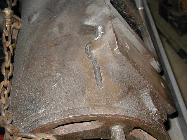
Photo #1 is another view of the grooved out crack and holes. Photo #2 shows welding the crack. Photo #3 shows skip welding around the crack, welding only 1/2" at a time and not starting the next weld until I can put my hand on the previous weld. The weld is done this way because I don't have the means to pre-heat the entire cylinder. Photo #4 shows the completed weld...


My friend Dave Yorks came over to the shop and had a little project he wanted to work on. He's working on a grinder / wire brush stand that will get belted up to one of his model engines. We are going to make a small flat belt pulley to replace the exiting "V" belt pulley...

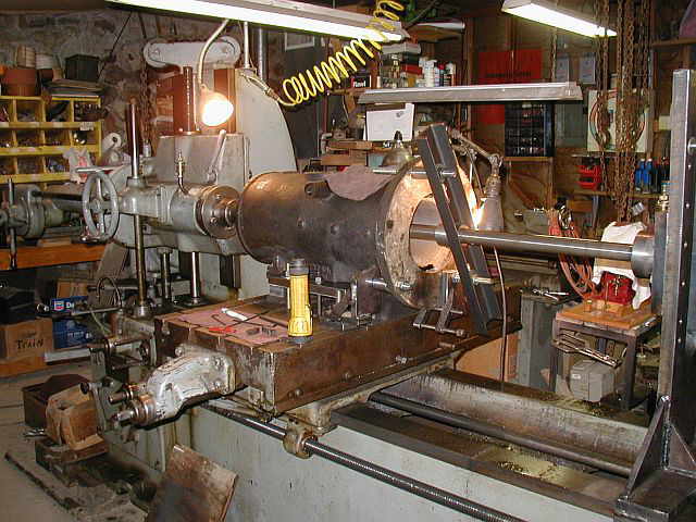
After grinding / smoothing out the weld, a thin coat of Devcon is applied to give the cast appearance over the weld. Photo #1 shows this. Photo #2 is another photo of the repaired area. Photo #3 shows the Bessemer cylinder back up on the Lucas HBM, ready for setup. Notice the nice parallels...


03/21/05 - 03/22/05
The first photo here shows the start of mounting the Bessemer cylinder to the Lucas HBM using some existing brackets that were made for another cylinder. One of these brackets is used on each side. Photo #2 shows cutting some 1" X 6" plate that will mount to the underside of the Bessemer cylinder where the intake valve chest and exhaust manifold mount. Photo #2 shows drilling the mounting holes in the 1" plate...


Photo #1 shows the first plate mounted on the bottom of the Bessemer cylinder, in position so the location of the machine table slots can be transfered to the plate and the holes drilled. After the holes were drilled, the plate was re-installed on the cylinder and in photo #2 you can see how the cylinder and plate are now clamped to the machine table. Photo #3 shows the second 1" thick plate mounted to the cylinder, needing the slot locations of the machine table transfered. The cylinder had to be removed from the machine table to mount the second plate...


Well the Bessemer cylinder is all mounted to the machine table. These (2) photos are of the setup. A good stable setup is a must when boring the cylinder. Next the head mounting studs will be removed and then the cylinder can be indicated into position...


03/24/05 - 03/26/05
The first photo here shows starting to remove the head mounting studs. (2) have been removed. New studs will be bought or made. We'll have to see how they measure up. Photo #2 shows running a 3/4-10 tap through each hole to clean up the threads. They are in very good shape. Sometimes if there in bad shape I like to helicoil them while setup on the HBM. Photo #3 shows the studs all removed, the threads cleaned up, and the head mounting surface cleaned up for indicating...


Photo #1 shows indicating the head mounting surface as close to the bore as possible. Photo #2 shows using a mirror to read the indicator at the bottom of the cylinder. Photo #3 shows tramming the bore. All (4) 90 degree quadrants are indicated and all the numbers written down. This is what I call, "mapping out the existing bore". Photo #4 shows the use of a coaxial indicator to get the HBM spindle on center of the existing bore. These measurements are all just starting points as things can be worn out real bad or even pitted. When boring a cylinder, this can be where most of the time is spent, the setup...


I decided to use a bearing support which will mount right to the cylinder and follow the cylinder along through the entire cut. This bearing support will be used along with the out board bearing. Photo #1 shows the bearing support being setup on the cylinder. Photo #2 shows the bearing support and the out board bearing all set up and a trail run being taken without a cutter in the tool holder. Photo #3 shows the first pass about 3/4 of the way through...


03/27/05 - 03/29/05
The boring continues on the 10 HP Bessemer cylinder. Photo #1 shows one of the first couple of roughing passes. Notice how the pitting really becomes visable as the new bore is machined. Photo #2 is an action shot of a roughing pass getting ready to enter the port area of the bore...


This is an interesting photo. It's taken looking in the exhaust port on top of the cylinder, as the cutter passes the port...

Photo #1 shows the entire setup for boring the 10 HP Bessemer cylinder. The Lucas HBM is boring the cylinder at the time the photo was taken. Photo #2 shows how many passes have been taken through the cylinder bore. We're down to just a few finish passes now...

Below is a small 15 second video clip taken from the rear of the Bessemer cylinder, crosshead side, showing one of the roughing passes. The chips are flying...

10 HP Bessemer Cylinder Boring Video Clip
03/30/05 - 03/31/05
Well here's the first look at the new bore. Photo #1 shows the boring bar and cutter head removed, looking in from the head end of the cylinder. The spots on the bottom of the bore are from oil dripping off the boring bar. Photos #2 & #3 are from the back end of the cylinder looking towards the head end. A total of .088 was removed from the old bore, that's .044 a side. A few more thousandth will be removed with honing...


Photo #1 shows cutting a 15 degree lead in angle to aid in, installing the piston rings. Photo #2 shows taking a machining pass on the head gasket surface with a 4" diameter shell mill. .012 was removed to clean up the head gasket surface. Photo #3 shows cutting in (2) grooves in the head gasket surface. These grooves help in holding the gasket in position and maintaining a good seal. Photo #4 shows the completed head gasket mounting surface. Now for the honing...


Here is a video clip of machining the head gasket surface...

Machining the Bessemer Cylinder Head Gasket Surface Video Clip
04/01/05 - 04/02/05
Photo #1 shows setting the hone up and getting it ready for work. Photo #2 shows moving the hone through the entire length of the bore. Photos #3 & #4 show what the bore is looking like after some honing. Kerosene is being used to keep the stones clean and lubricate the bore during honing...


This is a small video clip of Honing the 10 HP Bessemer bore...

Honing the 10 HP Bessemer Cylinder Bore Video Clip
04/04/05
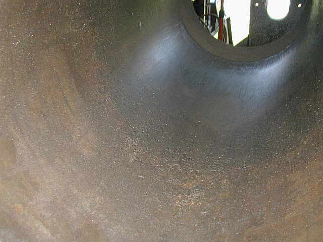
The honing of the bore is complete. Photos #1 & #2 are of the completed new bore. Photo #1 being from the head end, and photo #2 from the crosshead end. In photo #3 I tried to show how the cross hatching came out. It might be hard to see in the photo...


Photo #1 shows the Bessemer piston and rod in the lathe. The lathe is great for holding the piston why I remove the old rings and do some other work. Photo #2 shows the old rings all removed. Photo #3 is of the old rings. Not much tension left in the old rings. Photo #4 shows the piston ring keeper pins ground out of the ring grooves...


04/11/05
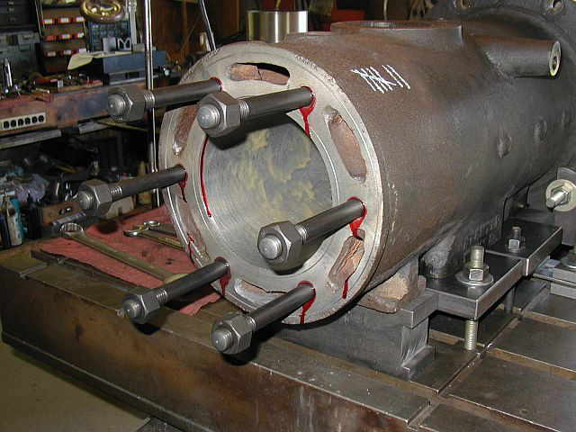
Photo #1 shows the new studs and heavy nuts for the 10 HP Bessemer cylinder. The stud on the right has been cut down to the proper length. Photo #2 shows cutting the studs to the proper length in the power hacksaw. Photo #3 shows turning the crown on the end of the stud in the lathe. Photo #4 shows (5) of the (6) studs completed. The machined surface is darkened with some chemical gun blueing to get the black finish...


In the first photo here you can see the new studs installed using some Loc-Tite. The yellow stuff in the bore is a wax type coating so the new bore doesn't rust. It's LPS #3 which can be bought in a spray can. Photo #2 shows the back end of the Bessemer cylinder mounting surface all cleaned up. Photo #3 is another photo from the back of the cylinder showing the wax coating on the new bore. Photo #4 shows the completed 10 HP Bessemer cylinder coming off the Lucas HBM...


The next job for the Lucas HBM will be a 10 HP Superior cylinder. Photos #1 & #2 show putting the Superior cylinder up on the HBM table. Photo #3 is a view looking in at the existing bore from the rear of the cylinder. Photo #4 is a view looking in at the existing bore from the head end of the cylinder...


Shop Work Continued on Page #37
Page 1, Page 2, Page 3, Page 4, Page 5, Page 6, Page 7, Page 8, Page 9, Page 10, Page 11, Page 12, Page 13,
Page 14, Page 15, Page 16, Page 17, Page 18, Page 19, Page 20, Page 21, Page 22, Page 23, Page 24, Page 25,
Page 26, Page 27, Page 28, Page 29, Page 30, Page 31, Page 32, Page 33, Page 34, Page 35, Page 36, Page 37,
Page 38, Page 39, Page 40, Page 41, Page 42, Page 43, Page 44, Page 45, Page 46, Page 47, Page 48, Page 49, Page 50,
for more Shop Work.
 |
Antique Gas Engine WebSite |
|
 Website designed and maintained by , Pavilion, NY.
Lunarpages Affiliate Program

Registered User #157284
Sun, Sparc, Ultra60 running Aurora 1.0 (RedHat Linux 7.3)
in mind, and are meant entirely for fun. No copyright infringements (if any) are done intentionally.