Shop Work Page #35

This webpage shows the current jobs
being worked on in the shop.
Hope you enjoy the activity.
Page 1, Page 2, Page 3, Page 4, Page 5, Page 6, Page 7, Page 8, Page 9, Page 10, Page 11, Page 12, Page 13,
Page 14, Page 15, Page 16, Page 17, Page 18, Page 19, Page 20, Page 21, Page 22, Page 23, Page 24, Page 25,
Page 26, Page 27, Page 28, Page 29, Page 30, Page 31, Page 32, Page 33, Page 34, Page 35, Page 36, Page 37,
Page 38, Page 39, Page 40, Page 41, Page 42, Page 43, Page 44, Page 45, Page 46, Page 47, Page 48, Page 49, Page 50,
for more Shop Work.
03/05/05 - 03/06/05
In this photo here my oldest son Joseph is doing some electrical work for wiring up the 3 HP 3 phase motor that is going to be used on the 12" Hendy Shaper...

Here in these (3) photos I made up (2) 6" long stainless steel hot tubes...


With almost all the machine work done on the 300 HP Miller piston, some final diameter checks are made on the OD of the piston. Hows that for a set of mics...

Now to get back to work on the motor mount for the shaper. Photo #1 shows the start of a new mounting bracket. Photo #2 shows a new plate made for bolting to the motor plate. Photo #3 shows setting some of the plates up to get locations. Photo #4 shows milling some clearance slots for the bolt heads...

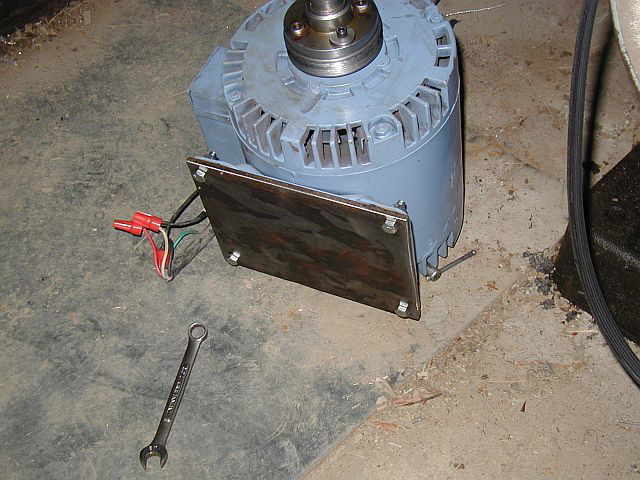


Photo #1 shows the clearance for the bolt heads. The side landed right under the motor mounting holes. Photo #2 shows welding the plates together. Photo #3 shows things really starting to take shape. Photo #4 shows welding a gusset on the bottom of the motor plate to really stiffen things up...


Photo #1 shows the gusset. Photo #2 shows how everything looks from the back side of the shaper. Photo #3 shows eveything completed from the front of the shaper. Boy does this motor run nice and smooth. It's made a new machine out of the shaper...


03/07/05 - 03/08/05
Here in these next few photos I finished up some work for a friend on his De Laval engine. Photo #1 shows the tag that's on the engine. Photo #2 shows one of the problems, a rusted in bearing race. Photo #3 shows (4) areas cleaned and (4) weld beeds put on the race and it is starting to come out of the housing...


Photo #1 shows the bearing race completely removed from the housing. Photo #2 shows the housing all cleaned up and ready for the new bearing race...


The same procedure was used on the bearing race in the main engine housing. Photo #1 shows the (4) cleaned areas ready to get a beed of weld. Photo #2 shows the bearing race removed from the engine housing. Photo #3 shows the engine housing ready for the new bearing race...


This brass tag for a C.P. and J. Lauson engine needed to have the serial number and HP stamped on it. Photo #1 shows the tag before stamping the numbers. Photo #2 shows the completed tag...


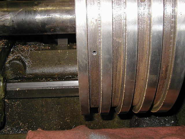
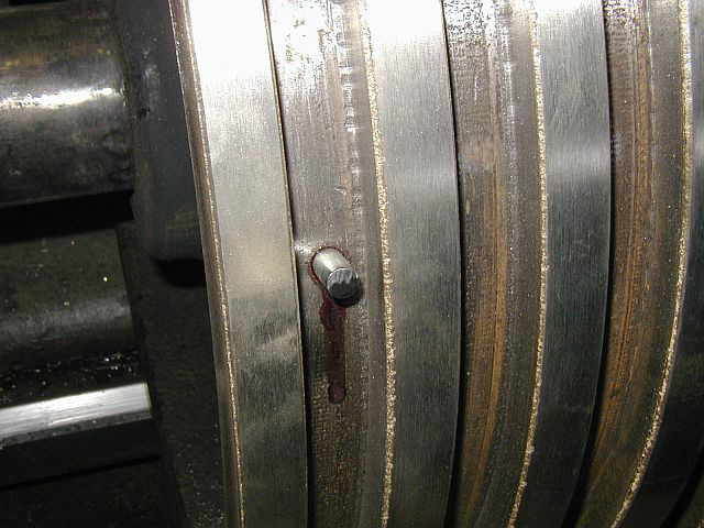
Here in these next few photos the last of the work on the 300 HP Miller piston gets completed. Photo #1 shows drilling a hole in the piston ring groove. Photo #2 shows tapping the hole to a 5/16-18 thread. Photo #3 shows a pin threaded into the hole with lock-tite applied. Photo #4 shows the pins in (3) of the (4) ring grooves. The top ring groove didn't have a pin in it for maintaining the ring orientation...


These (2) photos are of some finish work being done to the connecting rod and the lock nut, trying to clean them up...


03/11/05 - 03/13/05
Work is starting on making a bearing race insertion tool for the De Laval engine. Photo #1 shows facing and turning the OD to size. Photo #2 shows drilling a through hole to mount a handle to the bearing race driver. Photo #3 shows counter boring the driver for a 1/2" SHCS...


This next photo shows the bearing race driver turned around in the lathe chuck, facing and turning the other side. Photo #2 shows counter sinking or deburring the clearance hole for the 1/2" SHCS...


Photo #1 shows making a bearing race driver handle, turning the OD and facing the end. Photo #2 shows drilling and counter sinking a hole for the 1/2"-13 thread. Photo #3 shows threading the hole for mounting the handle to the bearing race driver. Photo #4 shows the completed bearing race insertion tool...


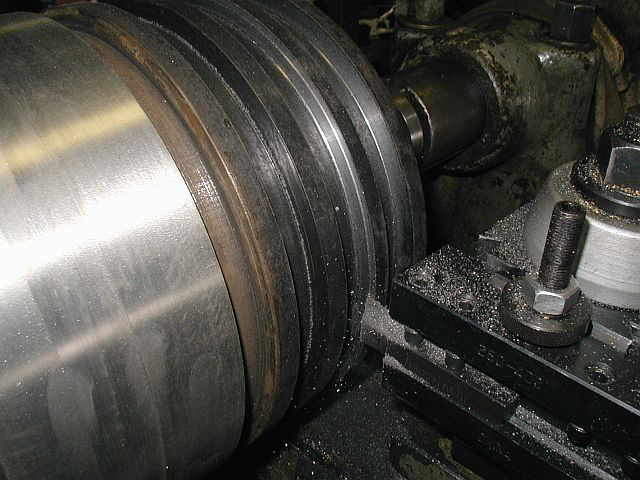
The first photo here shows loading the 20 HP Evans piston in the LeBlond lathe. Photo #2 shows starting to true up the left side of the piston ring grooves. Photo #3 shows truing up the right side of the piston ring grooves, finishing them all to the same width. Photo #4 shows the completed piston ring grooves all trued up...


Here in this photo the work is completed on turning the OD of a 6 HP Witte piston and truing up the (3) piston ring grooves...

With the bearing insertion tool completed the bearing races can now be installed. Photo #1 shows getting things setup in the press for pressing the bearing race into the cover plate. Photo #2 shows the bearing race all pressed into the cover plate. Photo #3 shows pressing the bearing race into the main engine housing. Photo #4 shows the bearing race all pressed into the main engine housing...


03/14/05 - 03/16/05
Well I have been going to do this for a long time and now that the 3 HP 3 phase motor is hooked up to the shaper and the 10 HP Bessemer cyclinder bore job requires them, I am going to make a couple of large parallels. Photos #1 & #2 shows a piece of stock, 2.500 x 3.500 x 11.500 in the shaper taking a few roughing passes. Photo #3 shows one side of the parallel roughed out...


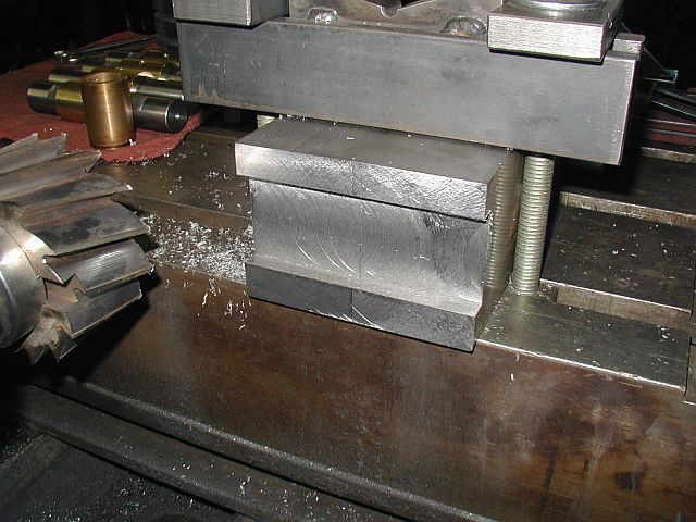
The next step after roughing on the shaper was to set the (2) parallels up on the Lucas HBM and clean the ends up and put in a 1.500 wide slot on each end. Photo #1 shows the first slot starting to take shape. Photo #2 shows the slot getting deeper. Photo #3 shows the completed slot on one side...


Now to clean up the rest of the ends. Photo #1 shows a 4" shell mill cleaning the first end up. Photo #2 shows the first end completed. Photo #3 shows the (2) parallels turned around 180 deg with the other end being trued up...


After truing up the ends the 1.500 diameter cutter is put back in the machine and the last slot machined in. Photo #1 shows the second slot taking shape. Photo #2 shows the completed ends and slots The parallels are starting to take shape...


After deburring the (2) parallels it's time to put them back on the shaper and complete the final machining. Photo #1 shows indicating the shaper table to insure that things will be square. Photo #2 shows the (2) parallels sitting on the table ready for clamping...


Shop Work Continued on Page #36
Page 1, Page 2, Page 3, Page 4, Page 5, Page 6, Page 7, Page 8, Page 9, Page 10, Page 11, Page 12, Page 13,
Page 14, Page 15, Page 16, Page 17, Page 18, Page 19, Page 20, Page 21, Page 22, Page 23, Page 24, Page 25,
Page 26, Page 27, Page 28, Page 29, Page 30, Page 31, Page 32, Page 33, Page 34, Page 35, Page 36, Page 37,
Page 38, Page 39, Page 40, Page 41, Page 42, Page 43, Page 44, Page 45, Page 46, Page 47, Page 48, Page 49, Page 50,
for more Shop Work.
 |
Antique Gas Engine WebSite |
|
 Website designed and maintained by , Pavilion, NY.
Lunarpages Affiliate Program

Registered User #157284
Sun, Sparc, Ultra60 running Aurora 1.0 (RedHat Linux 7.3)
in mind, and are meant entirely for fun. No copyright infringements (if any) are done intentionally.